Bringing Mechanisms to Life
Tl;DR
A workflow around: Python 2D ~ mbsd + CadQuery + blender
Intro
Its been a while since I read/studied Ingenieria del automovil: sistemas y comportamiento dinamico.
How about making a come back?
git clone https://github.com/JAlcocerT/3Design
git clone https://github.com/JAlcocerT/mbsd
graph TD
%% Node Definitions
SIM[Python Kinematic Simulator]
CQ[CadQuery Script]
DATA[Motion Data: JSON/CSV]
STEP[High-Res STEP/STL Files]
BLENDER[Blender Python Script]
PRINT[3D Printer / Slicer]
RENDER[Final Cinematic Animation]
%% Flow
subgraph "Phase 1: Logic & Engineering"
SIM -->|Calculates Kinematics| DATA
DATA -->|Feeds coordinates| CQ
CQ -->|Generates Geometry| STEP
end
subgraph "Phase 2: Manufacturing"
STEP -->|Export Static Parts| PRINT
end
subgraph "Phase 3: Visuals & Hand-off"
STEP -->|Import Geometry| BLENDER
DATA -->|Apply Keyframes| BLENDER
BLENDER -->|Materials & Lighting| RENDER
end
%% Styling
style SIM fill:#f9f,stroke:#333,stroke-width:2px
style CQ fill:#bbf,stroke:#333,stroke-width:2px
style RENDER fill:#bfb,stroke:#333,stroke-width:4px
style PRINT fill:#bfb,stroke:#333,stroke-width:4px###make creative #read the post to understand this :)
# Step 1 — build the scene
~/Applications/Blender4.2/blender --background --python blender_scene_creative.py
#Runs the Python script to build the scene — imports STLs, sets up materials, lighting, camera, bakes keyframes, and saves slider_crank_creative.blend. This is equivalent to make scene.
# Step 2 — render it
~/Applications/Blender4.2/blender --background slider_crank_creative.blend --render-anim
#blender --background slider_crank_creative.blend --render-anim
#Opens the already-built .blend file and renders all frames to video. This is equivalent to make render.
#rsync -avP jalcocert@192.168.1.2:/home/jalcocert/3Design/z-cadquery/render/slider_crank_creative.mp4 .
mpv slider_crank_creative.mp4This workflow replies to:
How does the mechanism move and what are the forces involved? Aka will it break while it operates?
How can I manufacture it? (Optional)
Before even manufacturing…does someone wants this new shiny invention? Aka: see how cool it renders
The Ecosystem
To get precision parts that are “ready to print” while also achieving “cool and realistic” animations, you are looking at a Hybrid Pipeline.
The industry-standard approach for an agent is to generate the geometry in a CAD-based (BREP/CSG) environment and then “hand off” that model to a Mesh-based (Blender) environment for the cinematic treatment.
BREP/CSG vs. Mesh: The Technical Divide
Understanding the difference is crucial for an AI agent, as the “logic” it uses to build the object changes entirely depending on the format.
BREP (Boundary Representation)
Used by: CadQuery, FreeCAD, SolidWorks.
- The Concept: Objects are defined by their mathematical boundaries. A cylinder isn’t a collection of points; it is a mathematical instruction: “A surface with radius R and height H.”
- Best for Precision: Because it’s math, you can zoom in infinitely and it’s always a perfect curve.
- Ready to Print? Yes. You can export to STEP (for CNC/molding) or high-density STL (for 3D printing).
- Agent Logic: “Find the face at $Z=10$ and drill a $5\text{mm}$ hole at the center.”
CSG (Constructive Solid Geometry)
Used by: OpenSCAD.
- The Concept: Objects are created by Boolean operations (Union, Difference, Intersection) on simple primitives (cubes, spheres).
- Best for Simplicity: It is very “logical.” To make a pipe, you subtract a small cylinder from a large cylinder.
- Ready to Print? Yes, but curves are often “faceted” (made of flat segments) unless you set the resolution very high.
Mesh (Polygonal Modeling)
Used by: Blender, Game Engines.
- The Concept: The object is a shell made of thousands of tiny triangles or squares (quads).
- Best for Visuals: This is how you do “cool and realistic.” You can distort the mesh, add “sculpted” details, or use “shaders” to make it look like rusted metal or glass.
- Ready to Print? Only if the mesh is “watertight” (no holes). Agents often struggle to keep meshes “non-manifold” (error-free for printing).
The Ideal Workflow for an Agent
If you want the best of both worlds, set your agent up with this two-step process:
Step A: The Engineering (CadQuery)
The agent writes a CadQuery script. This ensures the part is perfectly dimensioned and the holes align for 3D printing.
# Agent-generated CadQuery snippet
import cadquery as cq
result = (cq.Workplane("XY")
          .box(50, 50, 10)
          .faces(">Z").workplane()
          .hole(20))
# Export for printing
cq.exporters.export(result, 'part.stl')
Step B: The Animation (Blender)
The agent then runs a Python script inside Blender to import that STL and make it “cool.”
- Smoothing: Apply a “Remesh” or “Subdivision Surface” modifier to hide the facets.
- Materials: Apply a “PBR” (Physically Based Rendering) material (e.g., Anodized Aluminum).
- Physics: Add a “Rigid Body” simulation so the parts clank together realistically.
Why Not Just Use Blender for Everything?
If an agent tries to design a precision bolt-hole pattern in Blender using only mesh commands, it will eventually “break” the geometry.
If it needs to change the hole size later, it has to move hundreds of vertices manually. In CadQuery, it just changes a single variable: hole_dia = 5.
Conclusions
So here you have the working pipeline.
choco install blender --version=4.2.2 -y
#5.1.0
#wget https://download.blender.org/release/Blender4.2/blender-4.2.2-linux-x64.tar.xz
Oh, not a data pipeline this time.
There is “Pro” way to handle this.
We have the Logic (Simulator)
Wow you need the Geometry (CAD), and finally the Cinematics (Blender).
cd z-cadquery
& "C:\Program Files\Blender Foundation\Blender 4.2\blender.exe" --python blender_scene.py
& "C:\Program Files\Blender Foundation\Blender 4.2\blender.exe" --background slider_crank.blend
If you dont have a powerful GPU, you can consider such colab x blender combo
![]()
Since the kinematics are already resolved in Python, CadQuery is your best bridge because it lives in the same Python ecosystem.
We can import your simulator as a library directly into your CadQuery script.
The Three-Stage 3D Design Pipeline…
- The Geometry Engine (CadQuery)
Instead of hard-coding dimensions, you map your simulator’s variables to CadQuery parameters.
- Variable Mapping: If your simulator says
joint_ais at $(10, 5, 0)$, the agent writes a CadQuery function that places a bracket at those coordinates. - Assembly: CadQuery has an
Assemblyclass. You can define each part once and then use your simulator’s output (arrays of coordinates and rotations) to “pose” the parts for each frame.
- The Bridge (STL/STEP)
- For 3D Printing: Export the “Static” parts (the ones at rest) as high-resolution STLs.
- For Animation: You have two choices:
- Batch Export: Export an STL for every frame of the simulation (heavy, but foolproof).
- Single Export + Transform: Export each unique part once, and let Blender handle the movement using your simulator’s data.
- The Visual Engine (Blender)
This is where you make it “look cool.”
- Data-Driven Animation: You don’t need to manually animate. You can feed your simulator’s CSV or JSON output into a Blender Python script (
bpy). - The “Realism” Pass: * Beveling: In CAD, edges are mathematically sharp. In Blender, you add a “Bevel Modifier” to catch highlights, which is the secret to making 3D objects look “real.”
- Motion Blur: Since you have the kinematic vectors, Blender can calculate perfect motion blur for the moving parts.
Comparison of Logic Flow
| Feature | Simulator (Math) | CadQuery (Geometry) | Blender (Visuals) |
|---|---|---|---|
| Data Type | Vectors / Matrices | BREP Solids | Meshes / Shaders |
| Output | Coordinate Arrays | STL / STEP Files | MP4 / EXR Frames |
| Role | “Where is it?” | “What is it?” | “How does it look?” |
Understanding the Data Hand-off
To understand why this works, it helps to visualize how the data transforms from a “Point” to a “Solid” to a “Render.”
A Simple “Agentic” Workflow Strategy:
- The Simulator outputs a JSON file:
{"frame_1": {"arm_angle": 45.0, "base_pos": [0,0,0]}}. - CadQuery reads the JSON to generate the STL of the arm at that specific 45° angle for a 3D print check.
- Blender reads the same JSON. It takes a generic “Arm.stl”, places it at
[0,0,0], rotates it45.0degrees, applies a “Scratched Steel” material, and hits Render.
Outro
Why would you be doing D&A when agents are taking over?
Not sure if you are aware, but any of the ones in the leaderboard understand perfectly pbip files, lookML or simply…create awsome full stack web apps with FastAPI and Vite if you care enough just to put clear requirements.
No more excuses with DBs…Please
We have ChartDB, DBGate, …
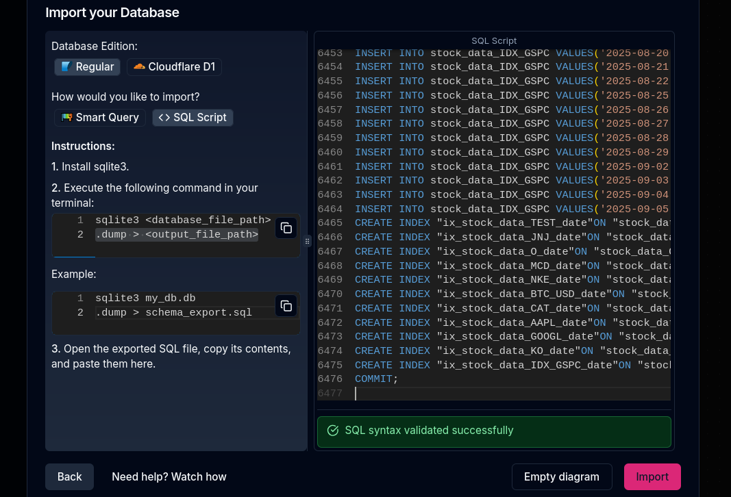
docker run -e OPENAI_API_KEY=<YOUR_OPEN_AI_KEY> -p 8080:80 ghcr.io/chartdb/chartdb:latest
# sqlite3 <database_file_path> #sqlite3 ./users.db #sqlite3 ./stock_cache.db
# .dump > <output_file_path>
#example
#sqlite3 ./stock_cache.db ".dump" > schema_export.sql && cat schema_export.sql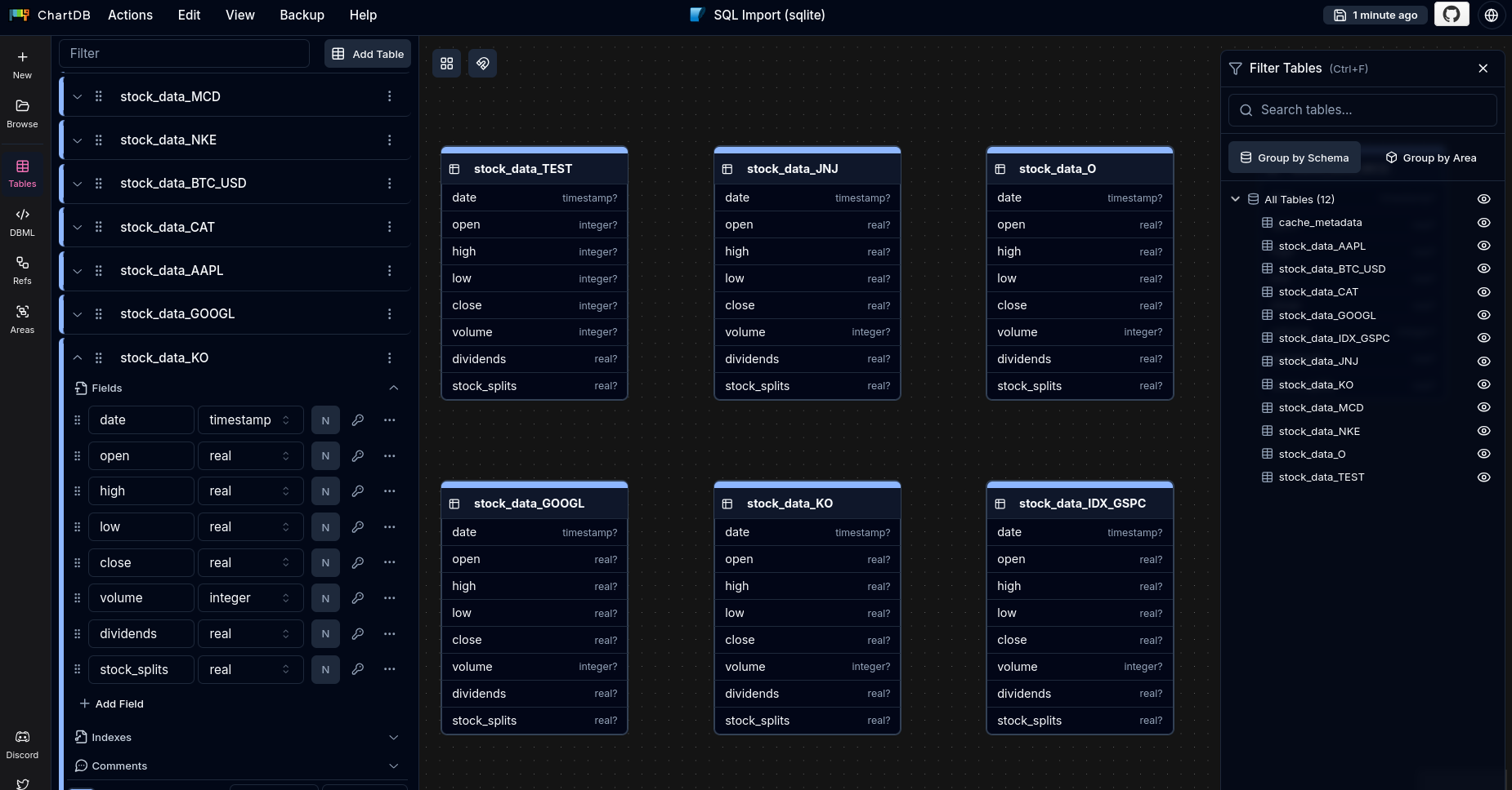
And specially:
- https://background-agents.com/ - Individual speed !+ organizational velocity :)
- https://arena.ai/leaderboard
- https://status.claude.com/ - Imagine the day that you’d be obsolete when this is down
claude
#/resume
#/remote-control
Isnt it time to do the mechanical engineering you always wanted to?
Or at least…to reflect whats the gas we are so concerned about now?
uv run tests/plot_historical_gweiss.py HESM --start 2015-01-01 --brand "@LibrePortfolio" --warmup-days 400Wasnt it just a Time travel machine to consume energy that left the sun ~250/300M years ago?
Isnt it just crazy…?
FAQ
Why CadQuery?
The choice between these three usually comes down to whether you want a GUI-first, Logic-first, or Code-first workflow.
For an AI agent driven by a Python simulator, CadQuery wins because it lives natively in the Python ecosystem, whereas the others require “handshakes” or custom languages.
Here is the direct comparison of why CadQuery is the superior choice for your specific “Simulator-to-CAD” pipeline:
- CadQuery vs. OpenSCAD (The “Logic” Gap)
OpenSCAD is great for hobbyists, but it is a “walled garden.”
- Language Barrier: OpenSCAD uses its own functional language. To connect it to your Python simulator, you have to write a Python script that generates a
.scadtext file, saves it, and then tells OpenSCAD to render it. This is “clunky” for an agent. - The “Fillet” Nightmare: In OpenSCAD, rounding an edge (a fillet) is incredibly difficult and computationally expensive. In CadQuery, it is a simple
.fillet(2)command. - Kernel Power: OpenSCAD uses CSG (Constructive Solid Geometry). It’s basically just adding and subtracting blocks. CadQuery uses BREP (the same engine as SolidWorks), which understands “faces,” “edges,” and “vertices” as distinct mathematical objects.
- CadQuery vs. FreeCAD (The “API” Gap)
FreeCAD actually uses the same geometry engine as CadQuery (OpenCASCADE), but their philosophies are opposites.
- GUI vs. Headless: FreeCAD is designed for a human to sit at a desk and click buttons. While it has a Python API, it is notoriously messy and “verbose” because it’s trying to manage a 3D interface at the same time.
- State Management: FreeCAD uses a “Document” model. You have to create a document, add an object, recompute the document, and manage the UI state. CadQuery is a stateless library; you just write code, and it outputs a model.
- Agent Friendliness: It is much easier for an LLM/Agent to learn the “Fluent API” of CadQuery (e.g.,
model.faces(">Z").workplane().hole(5)) than the complex object-tree manipulation required by FreeCAD’s Python console.
Comparison Table: The “Agent” Perspective
| Feature | CadQuery | OpenSCAD | FreeCAD |
|---|---|---|---|
| Integration | Direct Import: Just import cadquery. | External: Must write/read .scad files. | Heavy: Requires the full FreeCAD app/libs. |
| Geometry Engine | Professional (BREP/OpenCASCADE). | Basic (CSG/CGAL). | Professional (BREP/OpenCASCADE). |
| Readability | High (Chainable Python). | Medium (C-like syntax). | Low (Complex API calls). |
| Fillets/Chamfers | One-line command. | Hard/Experimental. | Standard, but API-complex. |
| Best For | Automated Pipelines & Agents. | Quick 3D Printing hacks. | Manual Human Design. |
- The “Secret Sauce”: The CadQuery Fluent API
Because your simulator already knows where the “Joints” are, CadQuery allows your agent to use selectors.
Instead of telling the CAD tool:
“Place a hole at $x=10.5, y=20.2$,” The agent can tell CadQuery: “Find the face pointing in the $+Z$ direction and put a hole at its center.”
This makes the code much more robust.
If the simulator changes the size of a part, the hole “follows” the face automatically because it was defined by intent rather than coordinates.
So…
- Use OpenSCAD only if you need a very tiny, lightweight script and don’t care about “professional” file formats like STEP.
- Use FreeCAD if you want to manually open the file later and tweak it with a mouse.
- Use CadQuery if you want a seamless, pure-Python pipeline where your simulator and your CAD model share the same variables in real-time.
About Euler Angles
In the world of 3D design and robotics, these are simply two different mathematical languages used to describe how an object is oriented in space.
Think of them as Directions vs. Rotations.
- Euler Angles: The “Human” Way
Euler angles describe a rotation as a sequence of three movements around the $X$, $Y$, and $Z$ axes.
You probably know them as Roll, Pitch, and Yaw.
- How they work: You rotate by $x$ degrees, then $y$ degrees, then $z$ degrees.
- The Order Matters: Rotating $X$ then $Y$ results in a different orientation than $Y$ then $X$. This is called “Rotation Order” (e.g., XYZ vs. ZYX).
- The Problem (Gimbal Lock): This is the “deal-breaker” for complex simulators. If you rotate one axis by $90^\circ$ so that it aligns with another axis, you lose a degree of freedom. The “gimbals” lock together, and the math breaks down because the computer doesn’t know which way is “up” anymore.
- Quaternions: The “Computer” Way
Quaternions are much harder for humans to visualize but are the “gold standard” for 3D engines like Blender, Unity, and high-end physics simulators.
- The Concept: Instead of three angles, a Quaternion uses four numbers $(w, x, y, z)$. It represents a single rotation around a specific vector (an imaginary line) in 3D space.
- Why they are better for Agents:
- No Gimbal Lock: They never “lock up,” no matter how crazy the rotation is.
- Smooth Interpolation: If your simulator has data for Frame 1 and Frame 10, Quaternions allow Blender to calculate the “in-between” frames perfectly (this is called SLERP).
- Computational Efficiency: They are faster for a computer to process than complex trigonometric Euler matrices.
| Feature | Euler Angles | Quaternions |
|---|---|---|
| Format | 3 numbers $(X, Y, Z)$ | 4 numbers $(W, X, Y, Z)$ |
| Readability | High (e.g., $90^\circ$ turn) | Low (Non-intuitive decimals) |
| Reliability | Risk of Gimbal Lock | Mathematically “Immune” |
| Usage | UI inputs, simple hinges | Physics engines, robotic arms |
Which one should a Simulator use?
- If your mechanism stays in a single plane (like a 2D scissor lift or a simple car steering): Euler Angles are fine and much easier for you to debug.
- If your mechanism moves in 3D (like a 6-axis robot arm or a drone): You must use Quaternions.
In Python, you don’t have to do the heavy math yourself.
Libraries like scipy.spatial.transform or mathutils (inside Blender) can convert between the two instantly:
Rendering on a mac M2
The first 2 steps are pretty straight forward on my x13 laptop.
But the rendering was taking ~8 min per image, despite dropping the resolution from 4k to 1080p at the script calling blender.
Luckily, a friend recently got a mac and I put the hands on it.
Like a geek, first thing I learn was how to open the terminal: CTRL+Tcmd
Then I installed brew:
Node and Python followed:
And after: *coudlnt resist to try CodeEdit
#npm install -g @openai/codex #https://github.com/openai/codex/releases/tag/rust-v0.118.0
npm install @openai/codex

cat <<'EOF' > package.json
{
  "private": true,
  "dependencies": {
    "@openai/codex": "^0.118.0"
  },
  "scripts": {
    "codex": "codex"
  }
}
EOF

codex
#/models
#/skilss
Remember about: https://skills.sh/
#npm install -g @anthropic-ai/claude-code #https://claude.ai/new
#claude
/login
/resume
#claude --dangerously-skip-permissions -p "promptwhateverrrr" #yolo
To get you from a fresh Mac to a professional, Linux-style dev environment, follow these steps in order. Open your default Terminal (found in /Applications/Utilities) and run these.
1. Install Xcode Command Line Tools
Before Homebrew can work, it needs the basic Apple compiler tools.
xcode-select --installA popup will appear; click Install.
2. Install Homebrew
This is your primary package manager.
/bin/bash -c "$(curl -fsSL https://raw.githubusercontent.com/Homebrew/install/HEAD/install.sh)"Important: After it finishes, look at the terminal output. It will give you 2-3 lines of code to run to add Homebrew to your PATH. They look like this (but copy the ones from your terminal):
echo 'eval "$(/opt/homebrew/bin/brew shellenv)"' >> ~/.zprofile
eval "$(/opt/homebrew/bin/brew shellenv)"
3. Install Git & Basic Utilities
Now that brew is ready, grab the essentials.
brew install git gh wget jq4. Install Language Managers (The Clean Way)
Instead of installing Node/Python directly, we’ll install the managers to keep your system clean.
For Node.js (via fnm):
brew install fnm
# Add fnm to your shell config
echo 'eval "$(fnm env --use-on-cd)"' >> ~/.zshrc
source ~/.zshrc
For Python (via uv):
brew install uv5. Install a Better Terminal & Editor
Since you want minimal and OSS, let’s grab Ghostty (the current favorite fast/minimal terminal) and Zed.
brew install --cask ghostty zed6. Verify Your Setup
Run these to make sure everything is linked correctly:
# Check Git
git --version

# Install and check Node (LTS version)
fnm install --lts
node -v

# Check Python (via uv)
uv --version
Pro-Tip: The “Mise” Alternative
If you prefer one tool to manage Python, Node, and everything else (very popular with Linux power users), run this instead of step 4:
brew install mise
echo 'eval "$(mise activate zsh)"' >> ~/.zshrc
source ~/.zshrc

# Then install versions easily:
mise use --global node@lts
mise use --global python@latest
To run docker in mac we will need something like QEMU or wsl
yea…a VM, as it cant run natively