Launching a MBSD framework?
TL;DR
The start of a system to ship mechanisms as a code: https://github.com/JAlcocerT/mbsd-core/releases
Intro
You know whats coming right?
The era of drag and drop its slowly going to an end.
And the time for concepts, semantics and orchestrating outcomes.
I consolidated the initial mbsd repo via: https://github.com/juliusbrussee/caveman just to save tokens.
Created: http://192.168.1.2:3034/hermesagent/mbsd/src/branch/oss-core-2d and pushed later to https://github.com/JAlcocerT/hermesagent/commits/tinker/hermesagent/mbsd/
Gabe Morris - Mechanism
The one I forked because its so great: https://github.com/JAlcocerT/mechanism
git clone https://github.com/JAlcocerT/mechanism
#choco install blender --version=4.2.2 -y #5.1.1
uv add mapbox-earcut
uv run blender-export/cam_to_stl.py
uv run blender-export/gear_to_stl.py
You can import the STLs to blender manually or with:
blender --background --python blender-export/blender_import.pyKinematics only.
No dynamics.
Evidence:
- Zero mass/inertia/torque/force-balance code in mechanism/. Sole “forces” mention = stray word in origin docstring (mechanism.py:270).
- Solver = vector-loop position/velocity/acceleration via numerical iteration. No Newton-Euler, no kinetics.
- Cam output = SVAJ (geometric). No follower spring/preload force calc.
- Gears = involute geometry only. No bending/contact stress, no power transmission.
- README confirms: “perform kinematic analysis by utilizing degrees of freedom”.
What you get = θ, ω, α, position, velocity, acceleration of points/vectors. What you don’t get = required
input torque, joint reaction forces, link stresses, dynamic balancing.
#git clone https://github.com/JAlcocerT/multi-body

git init && git add . && git commit -m "Initial commit: better ai docs" && gh repo create multi-body --private --source=. --remote=origin --push
#The trick
git submodule add https://github.com/JAlcocerT/mechanism.git external/mechanism
git commit -m "Add mechanism repo as submodule"
git submodule add https://github.com/JAlcocerT/mbsd.git external/mbsd
git commit -m "Add mbsd repo as submodule"
#git clone --recurse-submodules https://github.com/JAlcocerT/multi-body.gitComputational Mechanics
Repo = 2D MBSD simulator (Python) + e-book chaining engine NVH source→driver and suspension arc.
Simulator core (2D-Dynamics/)
- Saddle-point system: M·a + Cqᵀ·λ = Q, Cq·a = γ. Bodies, joints, constraints, contact, cam, terrain. - Outputs motions + Lagrange reactions.
E-book (z-destilled-ebook/) = 12 engine-NVH chapters + 4 suspension + 4 reference. Pipeline: cylinder → block → mounts → chassis → cabin → driver.
Examples under 2D-Dynamics/examples/:
- multi-cylinder-nograv/ — i4, boxer4, flat4, V, combustion, balance shafts, mounts, active damping,
chassis modal - suspension-terrain/ — quarter_car, road_profile_psd, design_space_sweep, active_suspension
- Adjacent: cam-follower, four-bar, pendulums, scotch-yoke, terrain-wheel
MBSD Framework Applications
From Augmented Reality Simulations, to engine balance, NVH, synthesis…
Engine Balance
Every engine in the MBSD series was analysed using the same tool: phasor analysis.
Each cylinder’s reciprocating inertia force is represented as a rotating vector at a given harmonic order ($1\times$, $2\times$, … engine speed).
Sum the vectors for all cylinders — if they cancel, that order is balanced; if they don’t, you have a free force or moment that will shake the engine.
The two sources of imbalance are:
- Free forces — net unbalanced force transmitted to the mounts and chassis
- Free moments (couples) — net unbalanced torque that rocks the engine about its mounts
The Phasor Method
For a multi-cylinder engine with crank throws at angles $\phi_k$, the $n$-th order force phasor for cylinder $k$ is:
$$\vec{F}_k^{(n)} = F_0 \cdot e^{j n \phi_k}$$
where $F_0 = m_r \cdot r \cdot \omega^2$ (rotating equivalent mass × crank radius × angular velocity squared). Balance requires $\sum_k \vec{F}_k^{(n)} = 0$ for each order of interest.
For in-line engines the moment check adds a $z_k$ arm (cylinder spacing along the crankshaft axis): $\sum_k z_k \cdot \vec{F}_k^{(n)} = 0$.
Engine Family Balance Map
| Engine | Config | Primary ($1\times$) | Secondary ($2\times$) | Free moment | Notes |
|---|---|---|---|---|---|
| I3 | Inline 3 | Balanced | Balanced | Yes — rocking couple | Characteristic 3-cyl rumble |
| I4 | Inline 4 | Balanced | Not balanced | No | $2\times$ shakers standard; balance shafts optional |
| I6 | Inline 6 | Balanced | Balanced | No | Perfectly balanced — smoothest inline config |
| Flat-4 / Boxer-4 | Horizontally opposed | Balanced | Balanced | Yes — offset couple | Cylinder offset creates hidden rocking moment |
| V6 (60°) | V-angle 60° | Balanced | Balanced | Yes — rocking couple | Mount tuning critical; dominant in compact cars |
| V8 Cross-plane | 90° V, 90° firing | Balanced | Balanced | No | Uneven bank firing → characteristic burble; US muscle |
| V8 Flat-plane | 90° V, 180° firing | Balanced | Not balanced | No | Even firing → high-RPM power; needs counter-rotating shafts |
| V10 | 72° V | Balanced | Balanced | No | Near-ideal; F1 standard before displacement limits |
| V12 | 60° V | Balanced | Balanced | No | Two I6 joined → inherently perfect |
Key takeaways from the series:
I4 is the most common compromise: primary balance achieved cheaply, secondary $2\times$ shaking accepted or suppressed with Lanchester balance shafts spinning at $2\omega$ in opposite directions.
Flat-plane V8 (Ferrari 458, Ford GT500R) trades the cross-plane’s moment advantage for even $90°$ firing intervals — every bank fires evenly, which improves exhaust scavenging and high-RPM breathing, but the $2\times$ secondary forces require counter-rotating balance shafts or stiff mounts.
Boxer-4 feels balanced on paper but the lateral offset between opposing cylinders ($\Delta z \neq 0$) produces a rocking couple that a true opposed-piston engine (with zero offset) would not have.
V12 is the engineering endpoint: two I6 crankshafts joined at the middle — every order cancels, no free moments, no balance shafts needed. Cost and length are the only constraints.
NVH
NVH (Noise, Vibration, Harshness) is what happens after the engine balance analysis.
Even a perfectly balanced engine produces vibration — combustion pulses, torque ripple, tyre inputs.
NVH engineering is the discipline of preventing that energy from reaching the driver.
The pipeline across the MBSD posts follows a single chain:
Engine (source) → Mounts → Block/Chassis → Suspension → Cabin → DriverEach stage has a transfer function that either amplifies or attenuates the vibration passing through it.
Stage 1 — Engine as a vibration source
The phasor analysis from the engine balance section quantifies what the engine puts into the mounts. Key outputs per engine family:
| Engine | Dominant free force | Dominant free moment | Peak amplitude (example) |
|---|---|---|---|
| I4 | $2\times$ vertical | None | 78.96 N secondary force |
| I5 | None | $1\times$ rocking | 66.56 N·m primary moment |
| V6 60° | None | $1\times$ rocking couple | Mount-position dependent |
| Flat-plane V8 | $2\times$ lateral | None | Needs counter-rotating shafts |
| Cross-plane V8 | None | None | Clean — rumble is firing-order acoustics only |
| I6 / V12 | None | None | Inherently zero — no shafts needed |
The rod ratio $R/L$ scales the $2\times$ component linearly — longer rods reduce secondary forces, which is why performance engines favour high rod ratios.
Stage 2 — Mount transmissibility
The engine sits on rubber or hydraulic mounts. Their job is to present high stiffness at low frequency (to locate the engine) and low transmissibility at the excitation frequencies. The 1-DOF transmissibility is:
$$T(r, \zeta) = \sqrt{\frac{1 + (2\zeta r)^2}{(1 - r^2)^2 + (2\zeta r)^2}}$$
where $r = \omega / \omega_n$ is the frequency ratio. Isolation only begins above $r = \sqrt{2}$, so the mount natural frequency $\omega_n$ must be placed well below the lowest engine harmonic:
| Mount type | Typical $\omega_n$ | Damping $\zeta$ | Best for |
|---|---|---|---|
| Soft rubber | ~8 Hz | 0.05–0.10 | Passenger car comfort |
| Stiff rubber | ~25 Hz | 0.10–0.15 | Sport / truck (load handling) |
| Hydraulic | Frequency-dependent | High near resonance, low above | Best of both — used in premium cars |
A 3-point mount layout for a transverse I4 (block mass ~150 kg, $I_z \approx 4,\text{kg·m}^2$) must be tuned so all 6-DOF rigid-body modes (lateral $F_x$, vertical $F_y$, pitch $M_{pitch}$, yaw $M_{yaw}$, roll $M_{roll}$) fall below the $2\times$ idle excitation frequency (~33 Hz at 1000 rpm idle).
Stage 3 — Suspension: the Pareto front
The quarter-car model (sprung mass $m_s$ + unsprung mass $m_u$, spring $k_s$, damper $c_s$) gives three conflicting objectives that cannot all be minimised simultaneously:
- Comfort — minimise sprung mass acceleration (cabin floor $g$-level)
- Road holding — minimise tyre load variation (contact patch stays loaded)
- Suspension travel — minimise rattle-space requirement
Sweeping $k_s$ and $c_s$ across the design space and evaluating all three metrics traces a Pareto front — any point on it is optimal in the sense that improving one objective worsens another.
Typical production pockets from the series:
| Segment | $k_s$ | $c_s$ | $\zeta$ |
|---|---|---|---|
| Luxury | ~15 kN/m | ~1000 N·s/m | 0.24 |
| Family | ~22 kN/m | ~1500 N·s/m | 0.35 |
| Sport | ~35 kN/m | ~2500 N·s/m | 0.50 |
| Truck | ~55 kN/m | ~4000 N·s/m | 0.62 |
The body-bounce resonance sits at ~1.3 Hz for a typical family car.
Passive damping that flattens this peak worsens high-frequency isolation — this is the fundamental Pareto trade-off.
Stage 4 — Active and semi-active control
Active control escapes the Pareto front by making $c_s$ frequency-dependent in real time.
- Skyhook — conceptually anchors the damper to an inertial frame (“the sky”) rather than relative velocity. Reduces body-bounce RMS by ~12% on smooth highway vs. passive baseline.
- Karnopp switching (semi-active) — approximates ideal skyhook using a controllable valve; switching transients cost ~4% performance vs. ideal but requires no hydraulic actuator.
- LMS adaptive filter (active) — feedforward controller using road preview; performance degrades when actuator delay pushes phase margin below 0° (Nyquist encirclement of $(-1,0)$).
The stability check for any active suspension loop uses the transfer function $G(s) = Y(s)/U(s)$ in the Laplace domain — poles in the right half-plane indicate instability, visible directly on a pole-zero plot without solving the full ODE.
ISO 2631 — the human weighting filter
All RMS metrics in the suspension and engine posts are implicitly frequency-weighted by ISO 2631, which models human sensitivity to vibration.
The weighting peaks around 4–8 Hz for vertical vibration (where humans are most sensitive) and rolls off at low and high frequencies.
A $2\times$ engine harmonic at idle (~33 Hz) is weighted lower than the body-bounce resonance at 1.3 Hz even if its raw amplitude is larger — which is why mount tuning focuses on the $\sqrt{2},\omega_n$ criterion rather than raw force magnitudes.
Synthesis
Mechanism analysis asks: given this linkage, what does it do?
Mechanism synthesis asks the inverse: given what it must do, what linkage should I build?
The synthesis posts introduce the three classical tools — one for each layer of the problem.
The three grandfathers of kinematic synthesis:
- Grashof → Does it work? — the feasibility check
- Freudenstein → What are the link lengths? — the algebraic design tool
- Burmester → Where do the pivots go? — the geometric construction for pose generation
Grashof — Feasibility
The Grashof inequality determines whether any link in a four-bar can rotate continuously ($360°$) or only rock:
$$s + l \leq p + q$$
where $s$ is the shortest link, $l$ is the longest, and $p$, $q$ are the remaining two. Depending on which link is grounded, the same set of link lengths produces four different mechanisms:
| Grounded link | Mechanism type | Motion |
|---|---|---|
| Adjacent to $s$ | Crank-Rocker | Short link rotates; output rocks |
| Short link $s$ | Double-Crank | Both sides rotate $360°$ |
| Opposite to $s$ | Double-Rocker | Both sides rock only |
| Non-Grashof ($>$) | Triple-Rocker | Trapped in an arc — no full rotation |
Real example from the cycling post — the human leg as a 4-bar at 60 RPM cadence:
| Link | Physical part | Length |
|---|---|---|
| Crank ($s$) | Pedal arm | 170 mm |
| Coupler | Lower leg (ankle→knee) | 440 mm |
| Rocker | Upper leg (knee→hip) | 400 mm |
| Ground | Frame (BB→hip) | 618 mm |
Grashof check: $170 + 618 = 788 \leq 400 + 440 = 840$ ✓ — crank-rocker, full pedal rotation achievable.
Freudenstein — Function Generation
Given three precision points (three pairs of input/output angles $\theta_i, \phi_i$), Freudenstein’s equation linearises the link-length ratios into a $3\times3$ system that can be solved directly by matrix inversion:
$$R_1 \cos\theta - R_2 \cos\phi + R_3 = \cos(\theta - \phi)$$
where $R_1 = L_0/L_3$, $R_2 = L_0/L_1$, $R_3 = (L_0^2 + L_1^2 - L_2^2 + L_3^2)/(2L_1 L_3)$.
Substituting the three precision points gives a $3\times3$ linear system in $(R_1, R_2, R_3)$ — no iteration, no nonlinear solver.
From those three ratios you recover the four link lengths directly.
This is the fastest route from a functional specification (“output must follow input according to this table of three values”) to a physical four-bar.
Burmester — Motion Generation
Where Freudenstein solves for function (angle-to-angle), Burmester theory solves for motion generation: the coupler must pass through a sequence of full poses (position + orientation).
For four prescribed poses, the locus of valid fixed pivot locations traces the center point curve (a fifth-degree algebraic curve).
Intersecting two such curves for the two pivots gives the complete set of four-bars that guide the coupler through all four poses.
Burmester synthesis introduces two classic problems that pure algebra misses:
- Order problem — the mechanism may visit the poses in A→C→B order rather than A→B→C
- Branch problem — reaching all poses may require physically dismantling and reassembling the linkage
Both are checked in simulation after synthesis via the Jacobian and position continuity tests.
Transmission Angle — The Design Diagnostic
Across both analysis and synthesis the single most useful scalar is the transmission angle $\mu$: the angle between the coupler and the output rocker.
Force efficiency scales as $\sin(\mu)$:
$$F_{useful} = F_{coupler} \cdot \sin(\mu)$$
At $\mu = 0°$ (toggle point) the output force drops to zero regardless of input — this is a kinematic jam.
The engineering floor is $\mu > 40°$ throughout the full cycle.
The transmission angle is a better early-warning metric than $\det(C_q) = 0$ (the mathematical singularity condition) because it is dimensionless, normalised, and has a direct physical interpretation.
The diagnostic checklist from the synthesis post:
| Check | Calculation | Catches |
|---|---|---|
| Newton-Raphson convergence | Position solve residual | Kinematic failure, Grashof violation |
| $\sigma_{min}$ of $C_q$ | SVD of Jacobian | Proximity to singularity |
| $\mu_{min}$ over full cycle | $\arccos$ of link vectors | Physical jamming, toggle points |
From Synthesis to Simulation
Once link lengths pass the Grashof and transmission-angle checks, the mechanism is handed to the constrained dynamics solver. The constraint equations $C(q, t) = 0$ encode the joint topology; the saddle-point system solves positions, velocities, accelerations, and Lagrange multiplier reaction forces in one step:
$$\begin{bmatrix} M & C_q^T \ C_q & 0 \end{bmatrix} \begin{bmatrix} a \ \lambda \end{bmatrix} = \begin{bmatrix} Q_{total} \ \gamma \end{bmatrix}$$
The Lagrange multipliers $\lambda$ are the joint reaction forces — the same forces that feed into FEM for stress analysis.
Synthesis provides the geometry; the MBSD solver provides the loads; FEM checks whether the chosen geometry survives them.
Conclusions
Believe it or not - this is another industry getting shaped by AI capabilities:
- Blender: photorealistic rendering, rigged animation, organic shapes, video editing — see
z-cadquery/blender_scene.py. - FreeCAD: assembly constraints, FEM simulation, technical drawings (TechDraw workbench), importing STEP/IGES from suppliers.
You have this ebook for context for your agents:
https://ebooks.jalcocertech.com/books/mechanism-analytics/
sudo apt install openscad
#cd ./Design/z-openscad
make animate FRAME=60
#  ffmpeg -stream_loop 9 -i slider_crank_os.mp4 -c copy slider_crank_os_10x.mp4
The sweet spot for OpenSCAD is parametric mechanical parts and automated STL pipelines — exactly what this folder does.
Because if mechanism 3D dynamics its kind of trivial now: at least with improved workflows like this one!
kinematics.py  ──►  OpenSCAD  ──►  CadQuery  ──►  FreeCAD  ──►  Blender
  (math)           (quick check)   (BREP/STEP)    (FEM/draw)   (render)
See the mindmap
Each tool has a distinct role — they are not interchangeable:
| Stage | Tool | Job | Output |
|---|---|---|---|
| 1 | Python (kinematics.py) | Solve positions, angles, constraints per frame | data.json |
| 2 | OpenSCAD | Fast visual sanity check; lightweight STL for prototyping | .stl, .png |
| 3 | CadQuery | Production-quality BREP geometry, exact fillets/threads | .step, .stl |
| 4 | FreeCAD | FEM stress analysis, tolerance checks, technical drawings | .pdf, .fcstd |
| 5 | Blender | Photorealistic commercial renders and animations | .mp4, .png |
Yea, openScad does not render as beautiful as blender does
You need some guardrails not to end up like this engine balance test
So… even more trivial is web development:
#git clone https://github.com/JAlcocerT/Slider-Crank
cd ./Slider-Crank/landing #https://multibodysystemdynamics.pages.dev/
And here is the JAlcocerTech whitepaper about AI powered design.
All models are wrong; some are useful.
To decide which one is the best fit for you:
 Consulting Services
 DIY via ebooks
Launching MultiBodySystemsDynamics
How could have I guessed that this domain was available to buy.
I made a quick web wrap: https://trends.google.com/
#git clone https://github.com/JAlcocerT/Slider-Crank #kineo bridge :) #https://multibodysystemdynamics.pages.dev/
#git clone https://github.com/JAlcocerT/multi-body
Superseeding this.
npm run build
#npx wrangler pages project create multibodysystemsdynamics
#https://multibodysystemsdynamics.pages.dev/
ping multibodysystemsdynamics.com
#whois multibodysystemsdynamics.com| grep -i -E "(creation|created|registered)"
#nslookup multibodysystemsdynamics.com
#dig multibodysystemsdynamics.com
With programmatic contact form, ofc.
About the “Authority Funnel” strategy.
In a high-stakes engineering field, this structure solves three problems at once: Identity, Validation, and Lead Generation.
Here is how those three components work together as a machine:
- The Landing Page (The “Hook”)
Since multibodysystemsdynamics.com is a long, formal name, the landing page must be visually light but technically heavy.
- The Hero Section: A high-quality 3D render or animation of a mechanism.
- The Value Prop: “We solve the mechanisms that others guess.”
- The Problem/Solution: Clearly state that you eliminate mechanical lock-up, branch defects, and vibration through rigorous algebraic synthesis.
- The Blog Section (The “Magnet”)
This is where you handle the “0 search volume” issue.
You don’t write for the masses; you write for the Search Intent.
- Topic Clusters: Write one post per chapter of your work.
- Example: “Why your 2D simulation is lying to you about gyroscopic stability.”
- Example: “Solving the 3-position synthesis problem in Python: A Burmester approach.”
- The Contact Form (The “Filter”)
Don’t just ask for an email. Use the form to qualify the lead.
Ask 2-3 technical questions:
- “What is your primary design challenge? (e.g., Path Generation, Force Balancing, 3D Dynamics)”
- “Are you looking for custom software, a one-time analysis, or a consultation?”
- Why? High-end clients prefer a form that asks for specifics. It tells them you are a professional who values time and understands the complexity of their problem.
Is this an epic launch?
The launch strategy: aka, focus strategy
In theory: for Non comercial purposes, MIT License :)
The Tier of Service: ~DIY ~DFY on demand
The Tech Stack:
| Requirement | Specification | Clarification / Decision |
|---|---|---|
| Frontend Framework | ||
| Styling/UI Library | ||
| Backend/Database | ||
| Authentication |
| Requirement | Specification | Clarification / Decision |
|---|---|---|
| Frontend Framework | Astro | |
| Styling/UI Library | Sassify MIT like theme | |
| Backend | ||
| Database | FireStore | |
| Authentication | Firebase Auth | |
| E-mail/ESP | MailTrap | |
| Analytics | Posthog | |
| Hosting | Container |
Whats next?
Understanding suspensions?
FAQ
This is how mbsd-core got started:
git clone https://github.com/JAlcocerT/mbsd/
git clone http://user:pwd@192.168.1.2:3034/hermesagent/mbsd.git local-mbsd
To publish after you create JAlcocerT/mbsd-core on GitHub:
cd /home/jalcocert/Desktop/mbsd-framework/mbsd-core git remote add origin https://github.com/JAlcocerT/mbsd-core.git git push -u origin main git push origin v0.1.0
git push origin v0.1.0 only pushes the tag. It does not necessarily create a full GitHub Release with notes/assets. GitHub may show the tag, but the polished release page is better created manually or with GitHub CLI.
Best option with GitHub CLI:
cd /home/jalcocert/Desktop/mbsd-framework/mbsd-core

gh repo create JAlcocerT/mbsd-core \
  --public \
  --source=. \
  --remote=origin \
  --push

gh release create v0.1.0 \
  --title "MBSD Core v0.1.0 - Week 1 Core" \
  --notes-file CHANGELOG.md
If the repo already exists:
git remote add origin https://github.com/JAlcocerT/mbsd-core.git git push -u origin main git push origin v0.1.0
gh release create v0.1.0 \
  --repo JAlcocerT/mbsd-core \
  --title "MBSD Core v0.1.0 - Week 1 Core" \
  --notes-file CHANGELOG.md
For the examples repo, I’d create it separately as: JAlcocerT/mbsd-examples
Purpose: Generated plots, GIFs, notebooks, richer mechanisms, educational material, and weekly demo drops for MBSD Core.
Suggested structure:
mbsd-examples/
README.md
LICENSE
examples/
  slider-crank/
  four-bar/
  mass-spring/
gallery/
  png/
  gif/
  mp4/
notebooks/
docs/
I’d use MIT there too unless you want media under a Creative Commons license.
Keep mbsd-core as the dependency, not duplicated code.
What’s in v0.1.0:
Three runnable examples copied from core:
- driven slider
- mass-spring-damper
- slider-crank analysis
Generated Week 1 PNG gallery:
- gallery/png/driven-slider.png
- gallery/png/mass-spring-damper.png
- gallery/png/slider-crank-analysis.png
Gallery regeneration script.
Smoke tests.
GitHub Actions CI for Python 3.10 to 3.13.
MIT license.
Changelog and release plan.
Verification passed:
4 tests passed all 3 examples run gallery generation works ruff check passed
Repo state:
repo: /home/jalcocert/Desktop/mbsd-framework/mbsd-examples branch: main commit: 64f0e25 tag: v0.1.0 status: clean
Publish order matters: push mbsd-core first, then mbsd-examples, because examples uses mbsd-core as a sibling/local source in dev and CI checks both out as siblings.
Commands after creating GitHub repos:
cd /home/jalcocert/Desktop/mbsd-framework/mbsd-core
git log --oneline
git remote add origin https://github.com/JAlcocerT/mbsd-core.git
git push -u origin main
git push origin v0.1.0

cd /home/jalcocert/Desktop/mbsd-framework/mbsd-examples
git remote add origin https://github.com/JAlcocerT/mbsd-examples.git
git push -u origin main
git push origin v0.1.0 gh release create v0.1.0 \
--repo JAlcocerT/mbsd-core \
--title "MBSD Core v0.1.0 - Week 1 Core" \
--notes-file CHANGELOG.md cd /home/jalcocert/Desktop/mbsd-framework/mbsd-examples
gh repo create JAlcocerT/mbsd-examples \
--public \
--source=. \
--remote=origin \
--pushIf it says it cannot add origin, that is fine if the repo was created. Then run:
git remote -v
git push -u origin main
git push origin v0.1.0
If origin is missing or wrong:
git remote add origin https://github.com/JAlcocerT/mbsd-examples.git
or, if origin already exists:
git remote set-url origin https://github.com/JAlcocerT/mbsd-examples.git
Then create the GitHub Release:
gh release create v0.1.0 \
  --repo JAlcocerT/mbsd-examples \
  --title "MBSD Examples v0.1.0 - Week 1 Examples" \
  --notes-file CHANGELOG.md
Quick pre-push sanity check:
git log --oneline
git status --short --branch

#Expected: bb070f4 Release MBSD Examples v0.1.0 candidate
 ## main
How did you started doing mechanical simulations?
It was actually long ago.
I got re-inspired by GabeMorris few years back.
Now with agents, there is no excuse not to do this just bc is not my job.
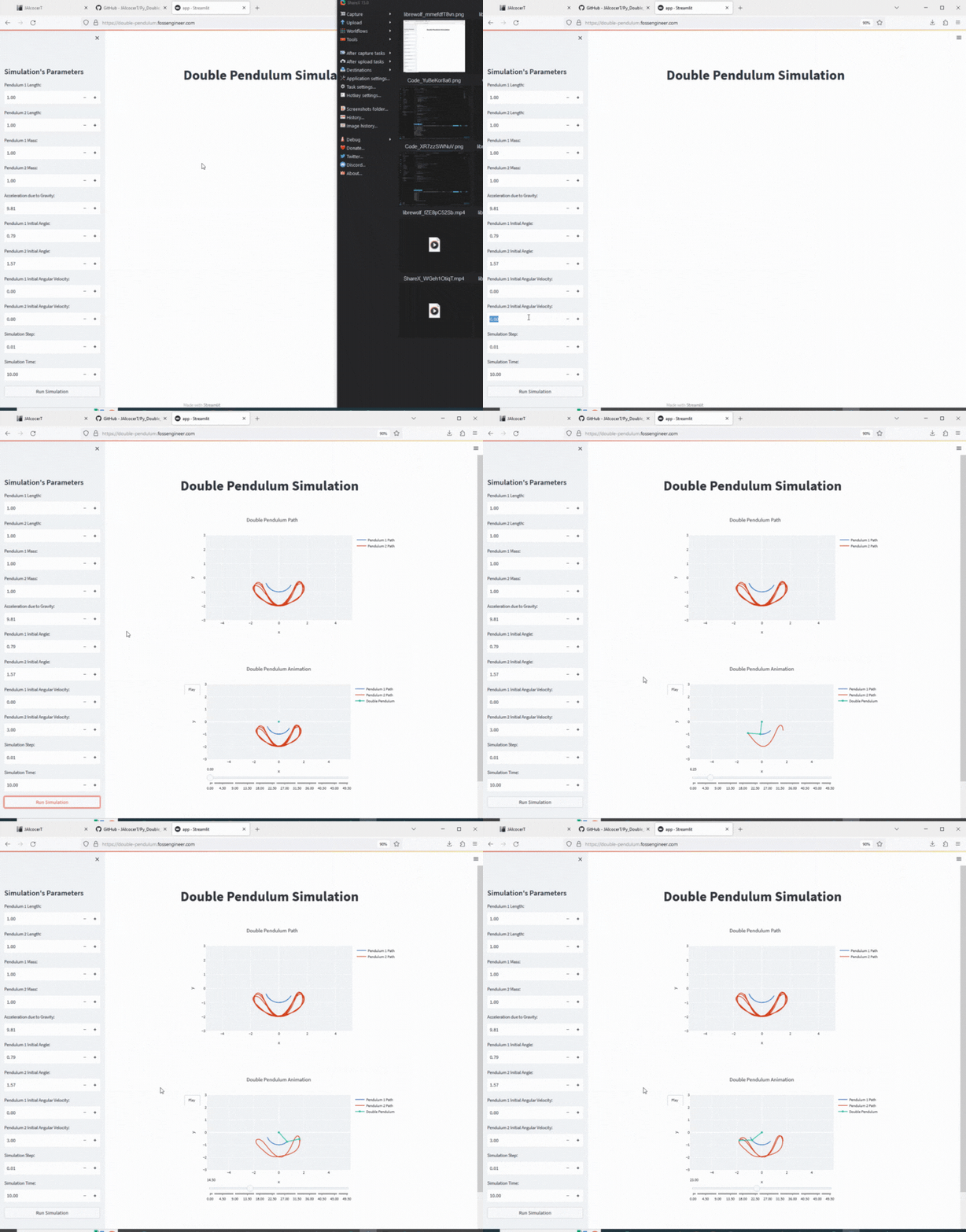 Double Pendulum Repo
 Double Pendulum Repo
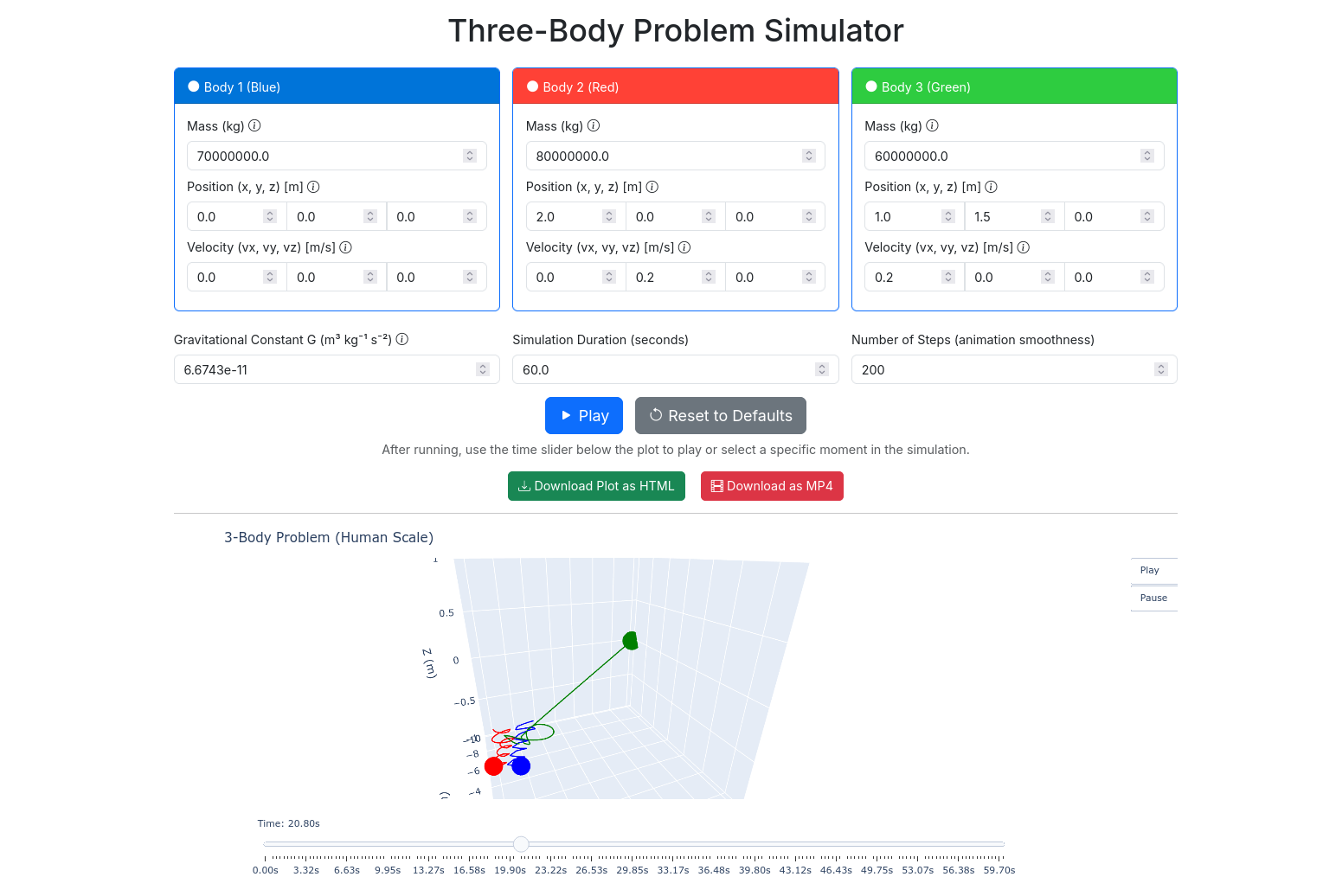 Three Body x FlasThree Bodies Web App
Agentic Blender?
Some references: https://github.com/agmmnn/awesome-blender
https://blendercam.com/ - An Open Source solution for CAM with Blender 3D