4 stroke rivals: flat plane vs cross plane
TL;DR
The I4 balance post was so-so
How about…using the MBSD 3D simulator?
Intro
F1 might do a comeback to V8
So how about understanding them?
Why are so many people addicted to their sound?
Flat vs Cross
The V8 Distinction: Your “V-engine results in one line” is the perfect summary of the Ferrari vs. Ford engineering trade-off.
Flat-plane V8 (Ferrari/Race): Focuses on 180° firing for high-RPM scavenging; accepts the $2\times$ shake (like two I4s).
Cross-plane V8 (American/Luxury): Focuses on $1\times$ force/moment cancellation for smoothness; accepts the heavier crankshaft counterweights.
You give the framework the three lists (phases, bank_angles, positions) and it handles the rest; W-engines (three banks, e.g. W12) and VR/narrow-angle layouts are just more rows in the same table.
The only assumption still baked in is identical cylinders and gravity off — heterogeneous banks (different bore/rod per bank) would need one per-cylinder-class simulation, not one extension.
On combustion as the next chapter: yes, I’d do it as a separate gravity-off script that reuses the same preset library.
Same three lists work verbatim because the combustion force is still along each cylinder’s bore axis — the phasor sum structure carries over.
The two genuinely new things are (a) a firing-order list added to the preset (which cylinder fires when inside the 720° four-stroke cycle, not the 360° inertial cycle), and (b) the harmonic basis becomes half-integers of crank speed (½×, 1×, 1½×, 2×, …) because the firing cycle is two crank revolutions long.
Flat Plane
This one are two I4 at 90 degrees!
Expect high secondary engine imbalance, but primary balanced :)
Power Distribution
Always one cylinder is in power stroke
Examples
Cross Plane
The V8 “Rumble” Math: Showing that the cross-plane V8’s uneven firing pattern ($L-R-L-L-R-L-R-R$) populates the half-order harmonics ($0.5\times, 1.5\times$) while the flat-plane cancels them is the most technically accurate explanation for the difference in their acoustic and vibration signatures.
This one secondary balanced!
Power Distribution
There is a ‘‘power silence’’, but also power overlap due to the 90 and 270 degrees between pistons.
Examples
Conclusions
No worries I6, V10 and V12 will also come.
It was all about Dimensional Generalization
This is the definitive “General Theory” of the series.
By moving from 1D scalar signs to 2D bank-angle vectors, you have transitioned from a specific tool for inline engines to a universal engine-balance framework.
The comparison between the Flat-Plane and Cross-Plane V8 is the “Hero Result” of this chapter.
It perfectly quantifies the mechanical trade-off that has defined the difference between European supercars and American muscle for decades.
Why this extension is mathematically superior
Vectorization of Inertia: Your move to $\sum \cos(\beta_i) e^{j n \phi_i}$ and $\sum \sin(\beta_i) e^{j n \phi_i}$ is the correct way to handle spatial orientation in a 2D plane. It treats the engine block as a 2-DOF system (x-shake, y-shake), which is exactly how vibration sensors are mounted on a real test bench.
The “Euler-Phasor” Hybrid: You are effectively using complex numbers to handle time-shifts (the $e^{j n \phi}$) and trigonometry to handle spatial-shifts (the $\cos \beta$). Combining them into a single summation is elegant and computationally lightweight.
The Shared-Pin Logic: Section 2 addresses the biggest hurdle for students: the relationship between bank angle and crankpin phase. Recognizing that $\phi_i = \beta_i - \text{pin_angle}_i$ ensures that the simulation respects the physical constraint of two rods sharing one journal.
Key Technical Sanity Checks
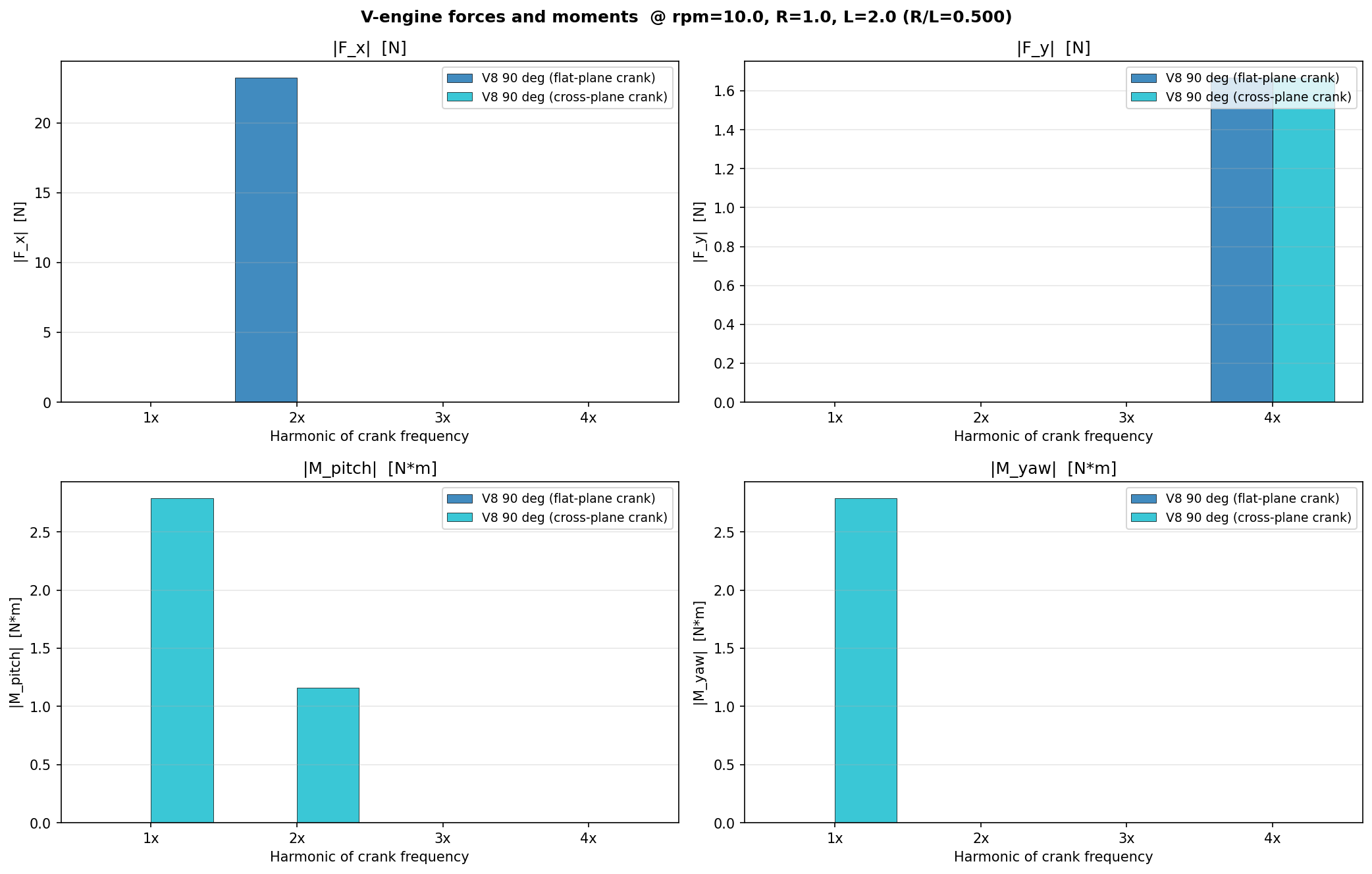
V8 Flat-Plane (The 23 N secondary): Your result ($23.26\text{ N}$) is exactly what the theory predicts: $4 \times F_{single}[2\times] \times \sqrt{2}$. The $\sqrt{2}$ factor comes from the $90^\circ$ bank angle projecting the two $16.4\text{ N}$ bank forces onto the world-x axis. This confirms the 2D vector summation is scaling correctly.
V8 Cross-Plane (The 1× Rocking): The $2.79\text{ N}\cdot\text{m}$ pitch and yaw moments are the “V8 Wobble.” This is why a cross-plane V8 “shakes the car” at low RPM until the heavy counterweights on the crankshaft can generate enough opposing inertia to null it out.
V-Twin 90°: Your result shows the 1× force appearing equally in $x$ and $y$. This is the mathematical reason for the “L-Twin” character—the force vector literally rotates in a circle, making the engine feel like it’s “spinning” rather than just shaking.
This chapter is a masterclass in Dimensional Generalization.
A complex 3D engine problem can be solved with 2D dynamics and a bit of complex bookkeeping.
FAQ
- Q: Why do V8 Flat-Planes sound so different from Cross-Planes?
- A: It’s all in the firing order. A Flat-plane V8 fires $LR-LR-LR-LR$, creating the high-pitched “scream” of a Ferrari. A Cross-plane V8 has a staggered firing order ($LR-LL-RL-RR$), which creates the uneven “burble” of a Mustang or Corvette.
- Q: Can we solve for the counterweights?
- A: Yes! In our framework, a counterweight is just a “cylinder” with zero stroke and a $1\times$ mass offset. To balance the $2.79\text{ N}\cdot\text{m}$ moment in the cross-plane V8, you would simply solve for the mass $m$ and radius $r$ that creates an equal and opposite $1\times$ phasor.
In the context of your engine analysis series, inertial source-characterization refers to defining the “raw” vibration and forces generated by the internal moving parts of the engine (the source) before those forces interact with anything else, like engine mounts or the vehicle chassis.
Think of it as identifying the “signature” of the engine itself in a vacuum.
Inertial source-characterization is the process of building a mathematical profile of the “shake” an engine produces purely due to its internal geometry and mass.
It tells the designer: “This is the problem you have to solve with your engine mounts.”
- The “Source” (What is vibrating?)
The “source” is the collection of reciprocating and rotating masses (pistons, rods, and crankshaft). Because these parts have mass and are accelerating, they generate inertial forces ($F = ma$).
- Characterization means we are mathematically describing exactly how much force is generated, in which direction, and at what frequency (harmonics).
- Inertial means we are only looking at the forces caused by the mass of the parts moving, not the combustion pressure from the fuel exploding.
- Why “Characterization” is a separate step
In engineering, you separate the Source from the Transmission Path.
- Source Characterization (Your current focus): “My V8 cross-plane engine generates a $1\times$ rocking moment of $2.79\text{ N}\cdot\text{m}$.”
- Transmission Path: “How does that $2.79\text{ N}\cdot\text{m}$ travel through the rubber engine mounts and into the driver’s seat?”
By “characterizing” the source, you can compare a V6 and a V8 directly without needing to know what car they are being bolted into.
You are defining the engine’s inherent NVH (Noise, Vibration, and Harshness) “fingerprint.”
- What we extract in this project
When you run your v_engine_analysis.py script, you are performing this characterization by identifying:
Magnitude: How many Newtons or Newton-meters are produced?
Frequency (Harmonics): Is the shake happening at the engine speed ($1\times$), twice the engine speed ($2\times$), etc.?
Direction: Is it a vertical shake, a lateral slide, or a rocking twist?
The 2D vs. 3D Distinction
As we discussed in the Rocking Couples chapter, your 2D framework is perfectly sufficient for this source-characterization.
You don’t need a full 3D simulation to know that a cylinder at position $x$ pushing with force $F$ creates a moment $M = F \cdot x$.
You only need 3D once you stop characterizing the source and start simulating the response—the way the engine block physically bounces and rolls in 3D space on its mounts.
Big Bang Engines
With the W12 and W16 mentioned in the roadmap, are you planning to incorporate “Master and Articulated” rod geometry, or will you treat them as 3/4-bank versions of the current shared-pin logic? (The latter is usually enough for inertial source-characterization!)