Heat Transfer (+ Go Solar PoC)
Tl;DR
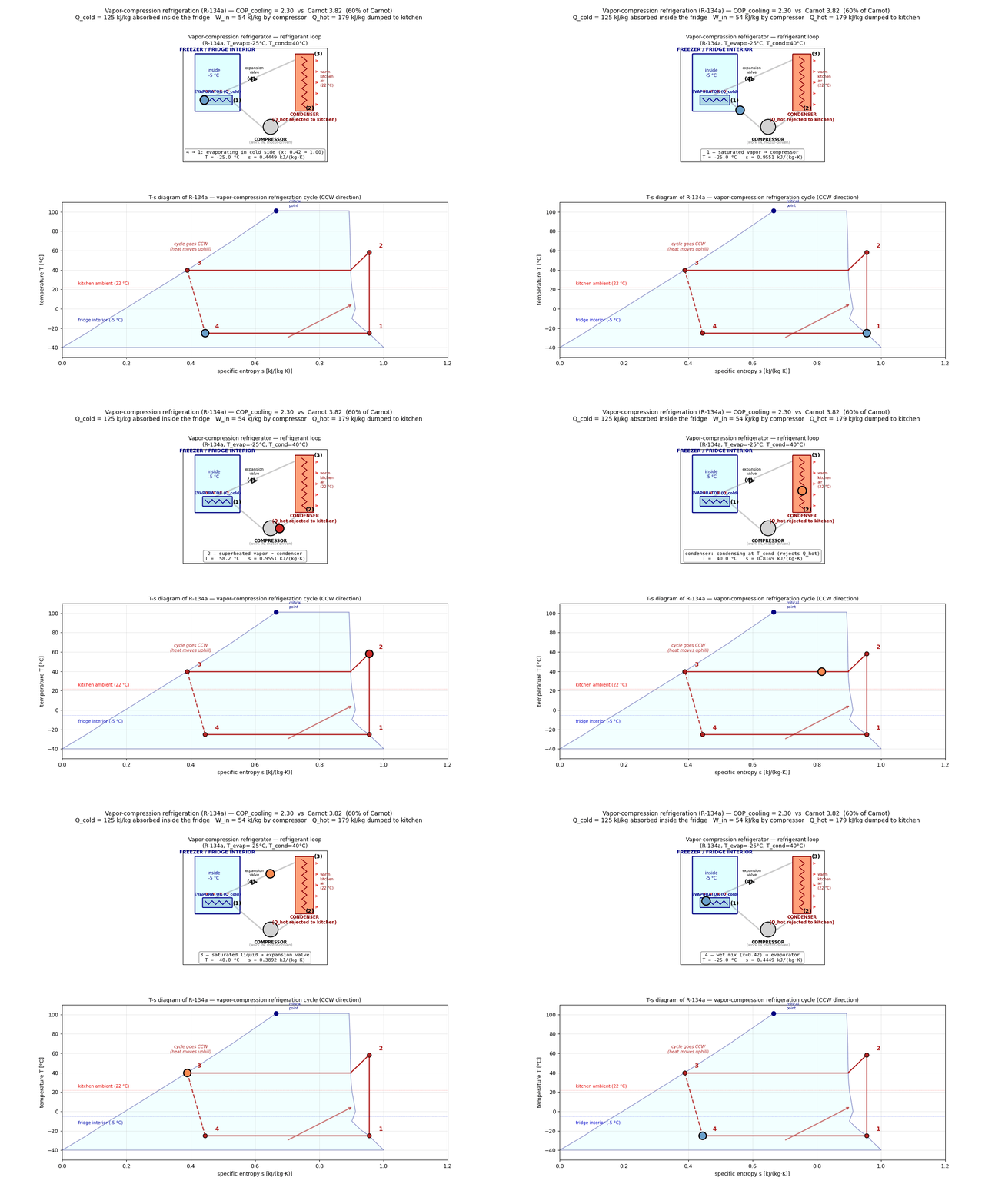
Intro
Who could have guessed that behind some IoT for watering plants you could find out the VPD concept.
That can be also very helpful if your are planning to automate the windows of a future greenhouse with a PID.
who.could.have.guessed.
But there is a more direct line back to the MBSD series.
Every engine post assumed rigid, isothermal parts.
In reality, a crankshaft running at 6000 rpm is also a heat exchanger — combustion gases heat the piston crown, the cylinder wall carries that heat to the coolant, and the material properties of every part change with temperature.
A crank that passes FEM at room temperature may fail at operating temperature because yield strength drops.
That is the domain of heat transfer.
The full engineering loop across these posts is:
| Discipline | Question | Feeds into |
|---|---|---|
| Fluid mechanics | Where do the combustion forces come from? | MBSD |
| MBSD | How do bodies move under those forces? | FEM + Heat |
| FEM | Does the part survive the mechanical load? | Design loop |
| Heat transfer | Does the part survive the thermal load? | Design loop |
The HEAT Physics
Heat transfer is the fourth leg of the engineering loop: fluid mechanics computes combustion forces, MBSD propagates them through the mechanism, FEM checks if parts survive mechanically — and heat transfer tells you whether they survive thermally.
In Electromagnetism, you have the four Maxwell’s Equations which cover everything from how charges create fields to how moving magnets create electricity.
In Heat Transfer, while there is one “Master Equation,” the complexity comes from the fact that heat moves in three fundamentally different ways.
You can think of it as one law that wears three different “outfits.”
The “Master” Equation (The Heat Equation)
The single equation you are likely thinking of is the Heat Diffusion Equation:
$$\frac{\partial T}{\partial t} = \alpha \nabla^2 T$$
This equation is the “boss.”
It describes how temperature ($T$) changes over time ($t$) across a space.
However, this primarily governs Conduction.
To actually solve a real-world problem, you have to “plug in” the specific laws for how heat enters or leaves the system.
The “Three Laws” of Heat Transfer
Unlike Maxwell’s equations, which are usually solved together, heat transfer is often broken down into these three distinct physical mechanisms:
A. Conduction (Fourier’s Law)
This is heat moving through a solid.
- The Law: $q = -k \nabla T$
- The Logic: Heat flows from hot to cold at a rate proportional to the material’s “conductivity” ($k$).
B. Convection (Newton’s Law of Cooling)
This is heat moving between a surface and a moving fluid (air or water).
- The Law: $q = h(T_s - T_\infty)$
- The Logic: The faster the fluid moves or the larger the surface area, the more heat is stripped away.
C. Radiation (Stefan-Boltzmann Law)
This is heat moving via electromagnetic waves (no medium required).
- The Law: $q = \epsilon \sigma (T_s^4 - T_{sur}^4)$
- The Logic: This is the “wild card.” Because it is $T^4$, doubling the temperature doesn’t double the heat—it increases it 16x. This is why lightbulbs and stars are so intense.
- Why it feels like “One Equation”
The reason it feels like there is only one equation compared to Electromagnetism is Energy Conservation.
In EM, you have to track Electric fields ($E$) and Magnetic fields ($B$)—two different entities that interact. In Heat Transfer, you are only tracking one thing: Internal Energy (Temperature).
Every heat transfer problem is essentially just an accounting balance:
[Energy In] - [Energy Out] + [Energy Generated] = [Change in Stored Energy]
The “Math Fight”
The reason people “fight” with this math isn’t because there are too many equations, but because of Boundary Conditions.
- Electromagnetism: You often deal with vacuum or uniform materials.
- Heat Transfer: You have to deal with the “real world” at the edges. One side of your metal plate might be touching cold water (Convection), while the other side is being hit by a laser (Radiation), and the inside is generating heat because of electricity (Joule Heating).
In short: You have one main “accounting” equation (The Heat Equation), but you have to use the three specific laws (Fourier, Newton, Stefan-Boltzmann) to define what is happening at the borders of your object.
Does comparing it to Maxwell’s equations make the “thermal circuit” idea (where $V=T$ and $I=q$) feel more or less intuitive to you?
Analogy - Heat vs Electr
The thermal-electrical analogy is a powerful mental model because it allows you to take the highly developed tools of circuit analysis—like Kirchhoff’s Laws and SPICE simulators—and apply them to physical cooling and heating problems.
This works because the fundamental physics of both systems follow the same diffusion and storage logic.
- The Core Mapping
To build a thermal “circuit,” you simply replace electrical variables with thermal ones:
| Electrical Component | Thermal Equivalent | Units |
|---|---|---|
| Voltage ($V$) | Temperature ($T$) | Volts $\rightarrow$ Kelvin ($K$) |
| Current ($I$) | Heat Flow ($q$) | Amps $\rightarrow$ Watts ($W$) |
| Charge ($Q$) | Thermal Energy | Coulombs $\rightarrow$ Joules ($J$) |
| Resistance ($R$) | Thermal Resistance ($R_{\theta}$) | Ohms $\rightarrow$ $K/W$ |
| Capacitance ($C$) | Thermal Mass ($C_{th}$) | Farads $\rightarrow$ $J/K$ |
- Translating the Components
When you look at a physical object, you “see” it as a circuit board:
Resistors (The Barriers)
In a circuit, a resistor slows down electrons. In heat transfer, a “thermal resistor” represents anything that slows down heat:
- Conduction: A thick piece of plastic has high thermal resistance; a thin piece of copper has low resistance.
- Convection: The air layer sitting on a heatsink acts like a resistor. If you turn on a fan, you are effectively “turning the knob” to lower that resistance.
Capacitors (The Buffers)
In electronics, a capacitor stores charge.
n heat, a capacitor represents Thermal Mass.
- A giant cast-iron skillet is like a massive high-voltage capacitor.
It takes a long time to “charge up” (get hot), but once it’s charged, it holds that energy for a long time even after the “power” (the stove) is turned off.
Current Sources (The Heat Gen)
A CPU, a laser, or a chemical reaction is modeled as a Constant Current Source.
It is pushing a specific amount of “Current” (Watts) into the system regardless of what the temperature is.
- Applying Circuit Laws
This is where the magic happens. You can use standard circuit rules to solve complex heat problems:
- Ohm’s Law ($V = IR$): Becomes $\Delta T = q \cdot R_{\theta}$. If you know your CPU is putting out 65W ($q$) and your heatsink has a resistance of 0.5 K/W ($R$), you instantly know the temperature rise will be 32.5 degrees above the room temperature.
- Kirchhoff’s Current Law (KCL): The heat flowing into a junction must equal the heat flowing out. This helps you track how heat splits between moving through a thermal pad versus moving through the air.
- Series vs. Parallel:
- Series: Heat moving through a CPU lid, then through thermal paste, then through a heatsink (like resistors in a single wire).
- Parallel: Heat escaping through the top of a device via a fan while simultaneously leaking through the bottom into the table.
- Where the Analogy Breaks Down
While brilliant, the analogy isn’t perfect. You have to be careful with two things:
Radiation: As we discussed, radiation is non-linear ($T^4$). In a circuit, this would be like having a resistor whose value changes drastically depending on the voltage. Most SPICE tools struggle with this without custom math.
Speed of Light vs. Speed of Heat: Electricity moves at near the speed of light. Heat is a “diffusion” process—it is slow and “sluggish.” While the equations look the same, the time constants ($\tau = RC$) in thermal systems are usually measured in seconds or minutes, rather than nanoseconds.
Does thinking of a “heatsink” as just a “resistor to ground” make it easier to visualize how to keep a component cool?
Applications
Heat transfer x VPD x DHT
In case you have some go-solar PoC system or you are just planting tomatoes and doing IoT/Big Data tech talks around:
#docker ps | grep emqx
cd ./RPi/Z_MicroControllers/RPiPicoW/picow-dht-webapp-vpd-poc
docker compose up -d --build
#Web → http://<host>:8001 · DB → localhost:5433.
docker compose up -d --build webapp
#docker compose up -d #and here it goes timescaleDB + all the webApp
#docker exec -it timescaledb psql -U pico -d sensors
#docker ps | grep timescaledbHeat transfer x MBSD x ICE
The physics of combustion is a thing on its own…
‘Bro started the video like an engineer and ended like a philosopher. Great video!’
In an ICE, only about 30% of the fuel’s chemical energy reaches the crankshaft as useful work.
- https://github.com/JAlcocerT/mbsd/blob/master/z-fluid-mechanics/dinamica-gases-py.md
- https://github.com/JAlcocerT/mbsd/blob/master/z-destilled-ebook/2d-slidercrank-multicylinder-combustion.md
The rest, must go somewhere: like those vibrations you try to avoid via nvh
Step 1 — Thermodynamic ODE. The same 0D ODE used throughout the enhancement scripts (Woschni heat transfer, Wiebe combustion, isentropic nozzle valves) is integrated over 2048 uniformly-spaced time steps covering 720° at n = 3000 rpm. Output: P(θ) at every sample point.
Step 2 — Force trace. F_wiebe(θ) = (P(θ) − p_a) · A_piston. Gauge pressure is used so the force is zero when the cylinder is at atmospheric (the reference load on the bearing from gas pressure alone, subtracting the atmospheric force that acts on both sides of the piston).
Step 3 — FFT. A single np.fft.rfft over 2048 samples gives the single-sided amplitude spectrum H_wiebe[k] for k = 0, 1, …, 8. These are the per-harmonic force amplitudes that the phasor framework consumes.
Step 4 — Phasor sums. ….
#Woschni heat transfer, Wiebe combustion
uv run ./mbsd/z-fluid-mechanics/combustion_analysis_wiebe.py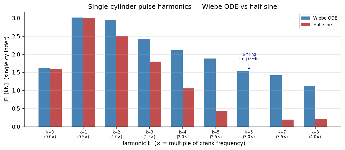
The general picture is:
| Energy path | Share |
|---|---|
| Crankshaft (useful work) | ~30% |
| Exhaust gases | ~30% |
| Cooling system (heat transfer problem) | ~30% |
| Friction and misc losses | ~10% |
The cooling system share is a heat transfer problem in exactly the sense of the theory above: conduction through the piston crown and cylinder wall, convection to the coolant, and radiation from the exhaust manifold.
Why it matters for the MBSD design loop:
- Piston crown: surface temperatures reach 300–400 °C during the power stroke. Steel yield strength at 400 °C is roughly 70% of its room-temperature value — so the FEM stress check must use temperature-dependent material properties, not datasheet values.
- Exhaust valves: face temperatures 700–800 °C. This is why exhaust valves are often sodium-filled (sodium melts and sloshes, carrying heat from the face to the stem) or made from Inconel instead of steel.
- Thermal expansion: a piston at 300 °C expands by roughly $\alpha \Delta T \cdot D \approx 12 \times 10^{-6} \times 250 \times 90 \approx 0.27,\text{mm}$ diametrically. This is why piston-to-bore clearances are set cold — the gap closes at temperature.
The heat path is: combustion gas → piston crown (conduction) → piston rings → cylinder wall (conduction) → coolant (convection) → radiator (convection + radiation). Each interface has a thermal resistance; minimising the total resistance is the thermal design problem.
Some time ago I had to make a fluid mechanics project in Matlab — it is time to bring it to Python.
Solar (Thermal) Power
Ive noticed some ppl doing cool things on the internet with these.
I could not resist to join the party.
No, i dont mean that you have to go off-grid
#streamlit run electronics-101/sample-pyscipe/solar_optimizer.py
#uv run streamlit run .\solar_optimizer.py
uv run  uv run ./electronics-101/sample-pyscipe\home-scale-pv\compare_systems.py
Just that you can estimate pretty acurately according to your latitude and few parameters how much can you get from the sun: coming frm this previous streamlit app and shaped by this brd
git clone /poc
cd ./poc/go-solar/
See the UI at:
localhost:3000
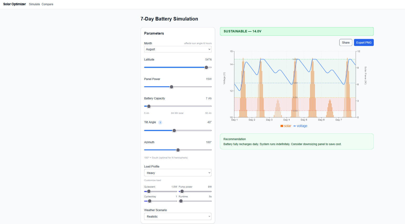
Its all about the latitude, the tilt, the day of the year… all those features :)
Tools
Assuming you are referring to PyScipe (the Python interface for SPICE circuit simulators), the search for a direct equivalent in heat transfer depends on whether you want to solve thermal problems using electrical analogies or physical simulation.
In engineering, heat transfer is often modeled using “Lumped Element” models where:
- Voltage ($V$) = Temperature ($T$)
- Current ($I$) = Heat Flow ($q$)
- Resistance ($R$) = Thermal Resistance ($R_{th}$)
- Capacitance ($C$) = Thermal Mass ($C_{th}$)
Because of this direct analogy, many engineers actually use PySpice itself to solve heat transfer problems by building a “thermal circuit.”
However, if you are looking for dedicated thermal libraries, here are the best equivalents:
- The Direct Functional Equivalent: Heatrapy
If you want a library that feels like a “simulator” where you define materials and watch heat flow, Heatrapy is the closest match.
- What it does: It is a lightweight framework for 1D and 2D thermal simulations using finite-difference methods.
- Best for: Simulating phase-change materials, caloric effects, and multi-material systems without needing a full CFD (Computational Fluid Dynamics) suite.
- Install:
pip install heatrapy
- The Professional Standard: OpenMDAO / NASA OpenSource
For complex thermal-fluid systems (like spacecraft or engines), many professionals use OpenMDAO.
- What it does: It’s an open-source framework for multidisciplinary analysis and optimization.
- Thermal link: It is frequently paired with thermal plugins to solve large-scale steady-state and transient heat transfer problems.
- The “Object-Oriented” Modeling: Modelica (via PyMarl / OMPython)
SPICE is to electronics what Modelica is to general physical systems (heat, mechanics, fluids).
- What it does: Modelica uses a “connector” approach very similar to a SPICE netlist. You can connect a “Heat Port” to a “Thermal Conductor.”
- Python Interface: You can use OMPython (OpenModelica) or PyMarl to script and simulate thermal models using the Modelica Standard Library.
- Specialized Tool: ThermoSim
For those specifically working on thermodynamic cycles and heat exchangers:
What it does: Focuses on mass and energy balances, heat exchanger design (evaporators, condensers), and power cycles.
Best for: Industrial applications and energy system design.
If you want to stay in the SPICE mindset (nodes, resistors, capacitors): Stick with PySpice and just label your units as Kelvin and Watts.
If you want to simulate physical objects/materials in 1D/2D: Use Heatrapy.
If you are building a complex machine (like a fridge or a motor): Use OpenModelica via Python.
To model the specific modes of heat transfer—conduction, convection, and radiation—the choice of tool depends on whether you want “Lego-style” connectivity or “Grid-style” physics.
Here is how those tools handle the specific physics:
- Modelica (via OMPython / PyMarl)
Modelica uses a Lumped Parameter approach. It treats physical parts as “components” with ports.
- Conduction: You use a
Thermal.Conductionelement. You input the thermal conductivity ($k$), area ($A$), and thickness ($L$). It solves $Q = \frac{k \cdot A}{L} \Delta T$. - Convection: You use a
Convectionelement. You must provide the heat transfer coefficient ($h$). It is excellent for “Fluid-to-Solid” interfaces. - Radiation: It has a specific
Radiationelement that handles the $T^4$ math (Stefan-Boltzmann Law). You input the emissivity and the view factor. - Pros: It’s the only one that easily handles Radiation and Convection out of the box for complex systems (like a radiator cooling an engine).
- Heatrapy (Pure Python)
Heatrapy is a Field-based solver. It divides a solid block into a grid of tiny points.
- Conduction: This is Heatrapy’s bread and butter. It calculates how heat “diffuses” through a material over time. It is much more accurate for seeing where a hot spot develops in a solid object.
- Convection/Radiation: This is where it struggles. You usually have to “fake” these by setting boundary conditions (e.g., telling the edge of the grid that it is losing a certain amount of energy to the air).
- Pros: If you want to see a heat map of a 2D metal plate, this is the tool.
- The “Electrical Analogy” (PySpice)
As mentioned before, if you use PySpice, you have to manually convert the physics into electrical components.
| Heat Mode | SPICE Component | Parameter |
|---|---|---|
| Conduction | Resistor | $R_{th} = \frac{L}{k \cdot A}$ |
| Convection | Resistor | $R_{conv} = \frac{1}{h \cdot A}$ |
| Thermal Mass | Capacitor | $C_{th} = m \cdot c_p$ |
| Radiation | Non-linear Resistor | Requires a “Voltage Controlled Current Source” because radiation is non-linear ($T^4$). |
The Radiation Problem: SPICE and Heatrapy struggle with radiation because radiation isn’t “linear.” Doubling the temperature doesn’t double the heat loss—it increases it by 16 times ($2^4$). Modelica is the only one in this list that handles this “natively” without you having to write custom math.
Which should you choose?
- Choose Modelica (OMPython) if you are building a System.
- Example: Modeling a satellite where heat comes from the sun (Radiation), moves through the frame (Conduction), and is released by a radiator (Radiation).
- Choose Heatrapy if you are analyzing a Part.
- Example: Modeling how long it takes for a specific iron rod to get hot at one end when the other end is in a fire.
- Choose PySpice if you are an Electrical Engineer.
- Example: You already have a circuit board designed in SPICE and you want to add a few “thermal resistors” to make sure the chips don’t melt.
Conclusions
Heat transfer closes the loop that MBSD, fluid mechanics, and FEM opened.
The combustion event produces forces (fluid), the forces drive motion (MBSD), the motion subjects parts to stress (FEM), and the same combustion event heats those parts — changing the material properties that FEM relied on.
Run them in sequence and you have a physics-grounded design loop.
Skip heat transfer and you are doing structural analysis with wrong material data.
I built some more
As per these next steps
The effect of variable valve timming - vvt
Forced induction (Compressor/Supercharger)
Diesel (CI vs SI)
Knock / detonation limit
Cylinder deactivation
torsional crankshaft dynamics
volumetric efficiency
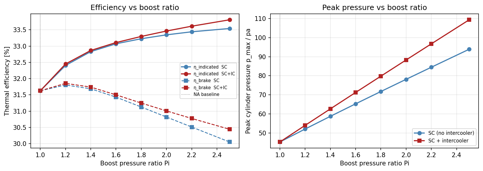
.md.FAQ
Can FreeCAD do this?
Yes. The FEM Workbench in FreeCAD handles thermal analysis alongside structural:
- Steady-state heat conduction: apply a fixed temperature to one face, a convective boundary condition to another (you supply $h$ and $T_\infty$), and CalculiX solves for the temperature field and heat flux through the part
- Coupled thermo-mechanical: run a thermal solve first, map the temperature field onto the structural mesh as a load, then run FEM — this is how you get thermally-corrected stress results
- Workflow: the same STEP geometry used for structural FEM works unchanged; you just switch the analysis type and boundary conditions
For the ICE use case: import the piston geometry from CadQuery, apply $T = 380,°C$ on the crown face and a convective BC ($h = 3000,\text{W/m}^2\text{K}$, $T_\infty = 90,°C$) on the skirt, run CalculiX, and read off the temperature gradient and peak heat flux.
A Minimal Heat Transfer Example in Python
The following simulates 1D transient conduction through a piston crown using finite differences — the same physics as the heat diffusion equation $\partial T / \partial t = \alpha \nabla^2 T$, discretised by hand:
import numpy as np

# 1D transient conduction through a piston crown
# Steel: k = 50 W/m·K, rho = 7800 kg/m³, cp = 500 J/kg·K
k, rho, cp = 50, 7800, 500
alpha = k / (rho * cp)   # thermal diffusivity m²/s ≈ 1.28e-5

L  = 0.010   # 10 mm crown thickness
N  = 20      # nodes
dx = L / (N - 1)
dt = 0.4 * dx**2 / alpha   # explicit stability: CFL < 0.5

T = np.full(N, 90.0)       # start at coolant temperature
T_hot  = 380.0             # combustion-side BC (°C)
T_cool = 90.0              # coolant-side BC (°C)

for _ in range(int(5.0 / dt)):   # simulate 5 s
    T[1:-1] += alpha * dt / dx**2 * (T[2:] - 2*T[1:-1] + T[:-2])
    T[0]  = T_hot
    T[-1] = T_cool

q_flux = k * (T[0] - T[1]) / dx   # W/m²

print(f"Steady crown temperature profile: {T[[0,N//2,-1]].round(1)} °C")
print(f"Heat flux into coolant: {q_flux/1e3:.1f} kW/m²")
# → same q you would plug into Newton's law of cooling to size the coolant flow
The boundary conditions here feed directly into the convection calculation: the heat flux $q$ at the wall is what Newton’s law of cooling ($q = h(T_s - T_\infty)$) must carry away. Size the coolant flow rate to handle that flux and you have closed the thermal design loop.
Combustion Models and Heat Release
The piston crown temperature used in the example above ($380,°C$) has to come from somewhere — that is the combustion model’s job. A combustion model computes the heat release rate $\dot{Q}(\theta)$ as a function of crank angle, which is what drives the in-cylinder temperature and pressure trace $P(\theta)$ from the fluids post.
Models are ranked by complexity and computational cost:
0D / Single-Zone Models (Thermodynamic)
The entire cylinder contents are treated as one uniform zone — one temperature, one pressure, one composition at each crank angle. All spatial gradients are ignored.
The Wiebe function is the workhorse here. It describes the cumulative heat release as an S-curve:
$$x_b(\theta) = 1 - \exp!\left[-a\left(\frac{\theta - \theta_0}{\Delta\theta}\right)^{m+1}\right]$$
where $\theta_0$ is the start of combustion, $\Delta\theta$ is the combustion duration, $a \approx 6.908$ (for 99.9% burn completion), and $m$ is a shape factor (~2 for SI engines, ~0.5 for diesel). The heat release rate is the derivative:
$$\dot{Q}(\theta) = Q_{total} \cdot \frac{dx_b}{d\theta}$$
This is cheap to compute and fits measured pressure traces well with two tuning parameters ($\Delta\theta$, $m$). It is the standard for engine cycle simulation tools (GT-Power, WAVE, Ricardo WAVE).
Heat transfer to the wall in a 0D model uses the Woschni correlation:
$$h_c = C \cdot B^{-0.2} \cdot P^{0.8} \cdot T^{-0.55} \cdot w^{0.8}$$
where $B$ is the bore diameter, $w$ is a characteristic gas velocity (function of mean piston speed and pressure rise), and $C$ is a calibration constant. This gives the convective heat transfer coefficient $h$ at each crank angle — exactly the $h$ that appears in Newton’s law of cooling.
2-Zone Models
The cylinder is split into a burned zone (products, high temperature) and an unburned zone (fresh charge, lower temperature), each with its own temperature. This adds:
- A flame front that propagates from the spark plug outward
- Separate energy equations for each zone
- More accurate prediction of knock (auto-ignition in the unburned zone) and NO$_x$ formation (strongly temperature-dependent)
Still 0D spatially, but captures the burned/unburned temperature split that a single-zone model misses.
Quasi-Dimensional (Flame Speed) Models
Add a geometric model of the flame front — typically a sphere expanding from the spark plug clipped by the cylinder walls.
The turbulent flame speed $S_T$ is modelled as a function of turbulence intensity $u’$ and laminar flame speed $S_L$:
$$S_T \approx S_L + u’$$
This links combustion to in-cylinder flow (tumble, swirl) without solving the Navier-Stokes equations.
Useful for sensitivity studies of combustion chamber geometry.
3D CFD Combustion Models (Full Spatial)
Solve the Navier-Stokes equations plus species transport and a combustion sub-model on a 3D mesh that moves with the piston and valves.
The main approaches:
| Model | Approach | Cost |
|---|---|---|
| RANS + flamelet | Time-averaged flow, tabulated chemistry | Hours per cycle |
| LES + flamelet | Resolved large eddies, tabulated chemistry | Days per cycle |
| DNS | All scales resolved, detailed chemistry | Research only |
OpenFOAM (via the reactingFoam or XiFoam solvers) is the main OSS option. XiFoam implements the flame wrinkling model for SI engines; reactingFoam handles diesel spray combustion with injector models.
Which Model for Which Question
| Question | Model |
|---|---|
| Engine cycle efficiency, BSFC | 0D single-zone + Wiebe |
| Knock prediction, NO$_x$ trend | 2-zone or quasi-dimensional |
| Combustion chamber shape optimisation | Quasi-dimensional |
| Injector spray, mixture formation | 3D CFD (OpenFOAM) |
| Wall heat flux map for FEM thermal BC | 3D CFD or Woschni on 0D |
For the MBSD design loop the practical answer is: run a 0D model with the Wiebe function to get the pressure trace $P(\theta)$ and the Woschni $h(\theta)$, feed the cycle-averaged wall heat flux into the FEM thermal analysis, and only go to 3D CFD if the combustion chamber geometry is what you are optimising.
About Tools
Modelica is a standalone language, while OMPython, PyMarl, and Heatrapy are Python-based tools or interfaces that allow you to stay within the Python ecosystem while solving physics problems.
- Modelica (The Language)
Modelica is a non-proprietary, object-oriented, equation-based language used to model complex physical systems (thermal, electrical, mechanical, etc.).
Think of it as a “Lego set” for engineers: you connect a “heat source” block to a “pipe” block, and Modelica handles the underlying math.
- Pros: Extremely powerful; handles “multi-physics” (e.g., how a hot motor affects a cooling fluid); huge library of pre-built components (Modelica Standard Library).
- Cons: It is a separate language from Python; has a steep learning curve; requires a “compiler” like OpenModelica or Dymola to actually run.
- OMPython (The Bridge)
OMPython is the official Python interface for OpenModelica. It allows you to control Modelica from within a Python script. You can load a Modelica model, change parameters, run the simulation, and pull the results back into a NumPy array for plotting.
- Pros: Best of both worlds—you get Modelica’s simulation power with Python’s data analysis (Matplotlib, Pandas).
- Cons: It requires a full installation of OpenModelica on your computer to function; the syntax for sending commands can feel a bit clunky compared to native Python.
- PyMarl (The Automation Specialist)
PyMarl is a more specialized Python wrapper for Modelica. It is often used for automating large batches of simulations or performing “parameter sweeps” (e.g., “What happens to the temperature if I test 100 different thicknesses of insulation?”).
- Pros: Simplified API compared to OMPython; great for researchers who need to run thousands of simulations in the background.
- Cons: Less flexible than OMPython if you need to build models “on the fly” from scratch in Python.
- Heatrapy (The Native Python Choice)
Unlike the others, Heatrapy is a “pure” Python library. It doesn’t need Modelica. It uses the Finite Difference Method to solve heat transfer specifically in solids and phase-change materials.
- Pros: No external software needed (just
pip install heatrapy); very easy to learn if you already know Python; specialized for things like phase-change materials (e.g., ice melting or solid-state cooling). - Cons: Much slower than Modelica for huge systems; limited to 1D and 2D heat transfer; doesn’t handle complex fluids (CFD) or mechanical parts well.
| Tool | Language Basis | Best For… | Difficulty |
|---|---|---|---|
| Modelica | Modelica (Unique) | Heavy industrial systems, vehicles, power plants. | High |
| OMPython | Python + Modelica | Using Python to analyze complex Modelica models. | Medium |
| PyMarl | Python + Modelica | Large-scale automation and “what-if” testing. | Medium |
| Heatrapy | Pure Python | Rapid prototyping of simple heat flow in solids. | Low |
Modelica itself is its own language.
Its files end in .mo.
However, the “Py” in PySpice, PyMarl, and PyMAPDL (another thermal tool) indicates that they are interfaces.
They act like a translator: you write Python code, and the interface translates it into the “native tongue” of the heavy-duty simulation engine running in the background.