Selfhosted IoT
TL;DR
Ok, you can buy this. Next please.
Intro
- WHY Im writting this post: Isnt it time to do some recap to IoT, HA and the solar panel?
- What Ive learnt with it: Ive ended up doing another tech talk and letting agents push new firmware via arduino CLI
Is it just about having few sensors and NFC tags enough?
Automatic plant watering?
Oh no…
will I also have to learn electronics, take into account electromagnetism to avoid EMF kickbacks
what else will it be?
That plants care about VPD and it would be great to know about thermodynamics and heat transfer?
suuuure
Last year, I was able to put together HA with a DHT connected to the Pico W powered by a solar panel.
But I left some few loose ends while documenting how great that setup was.
In the meantime… Ive made a small comeback to mechanisms electronics.
With the opportunity to make both, the esp32 and picow setups better
And planted couple of seeds for the first time.
Its time to make that IoT/Selfhosted setup better than I ever had.
Specially as I have also built some poc about how to go solar depending on your latitude, battery size, consumption…
cd ./poc/go-solarProtocols
Among all messaging protocols, mqtt has something to say.
Oh…no this is not regarding internet protocols like UDP and TCP.
But about ways to send information
Connecting to MQTT
- MqttX
- Mqtt Explorer
- MQTTy
- EMQx
Or simply with this CLI tool:
mosquitto_sub -h 192.168.1.2 -t "esp32/#" -v
#mosquitto_sub -h 192.168.1.2 -t "esp32/temperature/dht11"
Tools for MQTT
You can get inspired at: https://selfh.st/apps/?search=mqtt
Previously, Ive tinkered with:
httpie
reqable
emqx - which i recommend via container, as is a good companion for such DHT11 or DHT22 scripts
docker ps | grep emqxLike done at: https://github.com/JAlcocerT/RPi/tree/main/Z_MicroControllers/dht-webapp combining fastapi be, websockets and pgsql x timescaledb
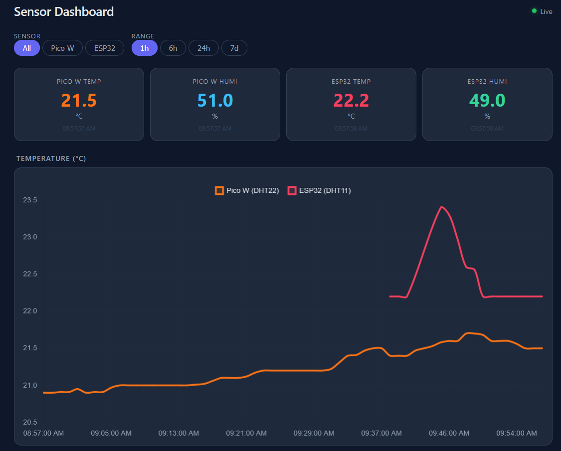
ESP x MQTT
For this post, ill be focusing on the ESP32
But the setup is also working for the PicoW.
Make sure that you see data flowing:
#mosquitto_sub -h 192.168.1.2 -t "pico/#" -v
#docker ps -a --filter "name=timescale"
docker exec -it timescaledb psql -U pico -d sensors -c "SELECT * FROM readings ORDER BY ts DESC LIMIT 5;"
And that there are two terminals active:
tmux lsSee
http://192.168.1.2:8077
You can also see whats the latest at the db:
#cd ./poc/iot-rpi-dht
sqlite3 /home/jalcocert/poc/iot-rpi-dht-insulation/ingester/data/readings.sqlite "SELECT COUNT(*), MAX(received_at) FROM readings;"

sqlite3 /home/jalcocert/poc/iot-rpi-dht-insulation/ingester/data/readings.sqlite "SELECT date(received_at) AS day, COUNT(*) AS rows, AVG(value) AS avg_value FROM readings WHERE device = 'pico' AND metric = 'humidity' GROUP BY day ORDER BY day;"

sqlite3 /home/jalcocert/poc/iot-rpi-dht-insulation/ingester/data/readings.sqlite "
SELECT
  date(received_at) AS day,
  ROUND(AVG(CASE WHEN device = 'esp32' AND metric = 'humidity' THEN value END), 2) AS esp_humidity,
  ROUND(AVG(CASE WHEN device = 'esp32' AND metric = 'temperature' THEN value END), 2) AS esp_temp,
  ROUND(AVG(CASE WHEN device = 'pico' AND metric = 'humidity' THEN value END), 2) AS pico_humidity,
  ROUND(AVG(CASE WHEN device = 'pico' AND metric = 'temperature' THEN value END), 2) AS pico_temp,
  COUNT(*) AS total_readings
FROM readings
WHERE device IN ('esp32', 'pico')
  AND metric IN ('humidity', 'temperature')
GROUP BY day
ORDER BY day;"


sqlite3 /home/jalcocert/poc/iot-rpi-dht-insulation/ingester/data/readings.sqlite "
WITH RankedReadings AS (
  SELECT
    device,
    metric,
    value,
    received_at,
    ROW_NUMBER() OVER (
      PARTITION BY device, metric
      ORDER BY received_at DESC
    ) AS rn
  FROM readings
  WHERE device IN ('esp32', 'pico')
    AND metric IN ('humidity', 'temperature')
)
SELECT
  device,
  metric,
  value AS latest_value,
  received_at AS last_seen
FROM RankedReadings
WHERE rn = 1
ORDER BY device, metric;"
ESP32 x MQTT x MLX90614
Few years ago, I wrote this post explaining how to use the MLX sensor with a Pi4 2GB.
pinout is the correct tool, and it confirms this is a Raspberry Pi 4B.
Use the J8 section:
J8: 3V3 (1) (2) 5V GPIO2 (3) (4) 5V GPIO3 (5) (6) GND
So your MLX90614 should be:
VIN -> 3V3 pin 1 SDA -> GPIO2 pin 3 SCL -> GPIO3 pin 5 GND -> GND pin 6
Its time to make the setup work with a ESP32 and MQTT.
#git clone /RPi
cd ./Z_MicroControllers/ESP32/esp32-c #just copy paste this one to Arduino IDE + CTRL U,
then, check with CTRL+M to see that the firmware is uploaded and that data flows…
Or try with:
mosquitto_sub -h 192.168.1.2 -t "esp32/temperature/mlx/#" -vThe “GY-906” part refers to the small blue or purple PCB (breakout board) that the sensor sits on.
As we discussed with the 3-pin DHT11, these breakout boards are designed to be “plug-and-play.”
If you look at the back of a GY-906 module, you will see tiny surface-mount resistors (usually labeled 103 or 472).
These are the I2C Pull-up resistors already soldered in place for you.
Because they are there, you don’t need to add your own on a breadboard.
- The Raspberry Pi has Built-in Pull-ups
This is a key difference between your previous Raspberry Pi project and your current ESP32 project:
Raspberry Pi: The specific pins you used (SDA/GPIO2 and SCL/GPIO3) have physical 1.8kΩ pull-up resistors hardwired onto the Raspberry Pi board itself.
Even if your sensor module didn’t have resistors, the Pi provides them automatically for I2C.
ESP32: Unlike the Pi, the ESP32 does not have physical pull-up resistors on its pins.
It only has “weak” internal software pull-ups.
ESP32 x MQTT x HM
How about sensing if some obstacle is present?
You can do it with this .cpp script, arduino IDE and CTRl+U
mosquitto_sub -h 192.168.1.2 -t "esp32/ir/#" -v
Youyour agents can also upload new firmware to the esp32/picoW with arduino-CLI
ESP32 x LCD
Why not displaying the info that is been sent?
ESP32 x MQTT x HMC5883L
Adding the HMC5883L (a 3-axis digital compass/magnetometer) is actually very easy because it uses the exact same “language” as the MLX90614: I2C.
Aka ESP32 x MQTT x Magnetometer
Since you already have the MLX90614 connected to D21 and D22, you don’t need to find new data pins.
You can simply “chain” them together.
- The Wiring (The I2C “Bus”)
In I2C, multiple sensors share the same two data lines.
The ESP32 tells them apart by their unique internal “address.”
| HMC5883L Pin | ESP32 Pin (GPIO) | Note |
|---|---|---|
| VIN / VCC | 3V3 | Power (keep everything on 3.3V) |
| GND | GND | Ground |
| SDA | D21 | Shares this pin with the MLX90614 |
| SCL | D22 | Shares this pin with the MLX90614 |
| DRDY | Leave Empty | “Data Ready” - usually not needed for basic projects |
- Is there anything “special” for this one?
Yes, the HMC5883L has one specific quirk you should be aware of:
The Voltage/Chip Confusion: There are two chips that look identical: the original HMC5883L and the newer QMC5883L.
- If you bought it recently, it’s likely a QMC5883L.
- They look the same, but the code for one won’t work for the other because they have different I2C addresses.
- Tip: If your code says “Sensor not found,” try a library specifically for the QMC version.
- Does it need a resistor?
Like your other modules, if the HMC5883L is on a small PCB (usually blue), it has the pull-up resistors built-in.
However, because you are now putting three devices on the same power line (DHT11, MLX90614, and HMC5883L), make sure your wires are tight.
If the power dips, the compass is usually the first thing to give weird readings.
- Why add a Compass?
While the DHT11 tells you the “environment” and the MLX tells you the “target,” the HMC5883L tells you orientation.
Orientation: It measures the Earth’s magnetic field.
Interference: Because it’s a magnetometer, try to keep it away from magnets, motors, or even the ESP32’s own metal shield, as they can interfere with the “North” reading.
Summary of your “Super-Sensor” ESP32:
- D4: DHT11 (Temperature/Humidity)
- D21: SDA for both MLX90614 and HMC5883L
- D22: SCL for both MLX90614 and HMC5883L
ESP32 x Water Pump
Time to put this together:
Yep, it pushes 1L in ~12 seconds with those 20w consumption!
See it powered via the bluetti:
This has been a journey with prep work for the ESP32 to work with the water
First this one with the BMS x 3s 18650 working like so
Then, a timed smoke test loaded to the ESP32 to wait 10s, push water for 3, then just keep blinking
Wrapping it all together and instead of a hard coded logic, one that I can control via mqtt when the esp32 will move the pump - *This is a good addition to my
./poc/iot-dashboard
How I did that?
First, recapping the logic of the 3wire fan setup with PWM control over mqtt. This one.
The mosfet was not heating and everyone was happy.
But that was only pulling ~0.2A, now, the pump will demand ~1.5A
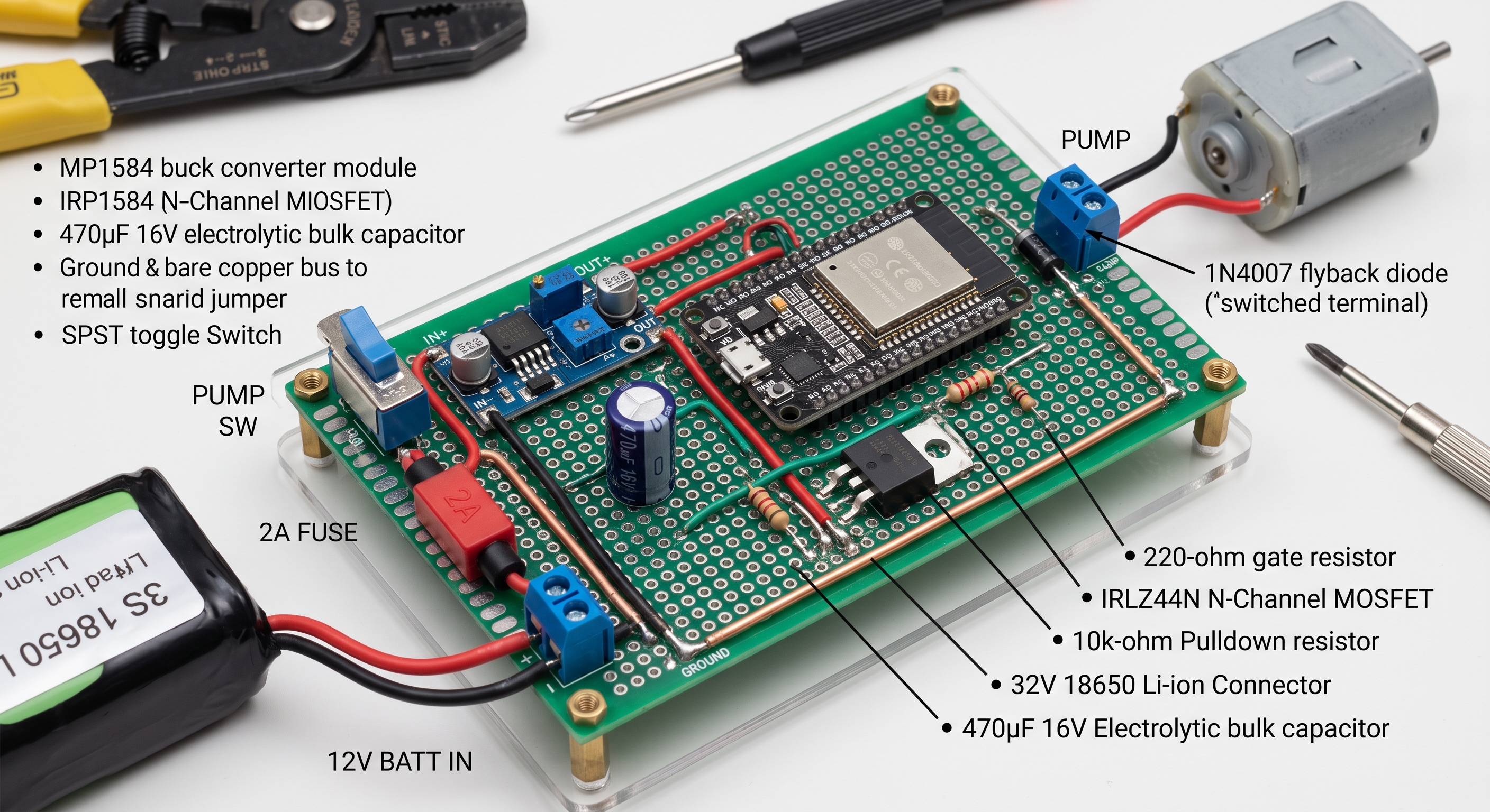
So…time to test: From the ESP32’s perspective, there are only three wires in total connected to its pins:
VIN(5V): Power in from the buck converterOUT+.GND: Return path to the buck converterOUT-(which shares ground with battery negative and the MOSFET source).GPIO23: That single output signal wire going to the 220 $\Omega$ gate resistor going to the MOSFET to control it.
Everything else (the 10k pulldown resistor, the MOSFET, the pump, the diode, and the 12V rails) sits on the power board/breadboard side.
BTW, Thinking of it as 3 sections is the most accurate and practical mental model for building and troubleshooting it:
- 1. The Supply Domain (Battery & BMS):
The raw energy source. It delivers unregulated ~9 V–12.6 V on the high side and protects against short-circuit, over-current, and cell under-voltage on the low side (
P-). - 2. The Logic Domain (Brain & Regulation): The low-power 5 V and 3.3 V system. This includes the MP1584 buck converter and the ESP32. It only handles milliamps of current and needs clean, quiet voltage rails to avoid brownouts and resets.
- 3. The Power/Load Domain (Actuator & Switch): The high-current, noisy circuit. This contains the pump, the flyback diode, the fuse, the manual switch, and the MOSFET’s drain-to-source channel carrying that 1.7 A.
The domains separate logically, but they touch at two specific crossover points:
- The Gate Resistor: The ESP32 (Logic) talks to the MOSFET Gate (Power) via that single wire through the 220 $\Omega$ resistor.
- The Shared Ground: All three domains tie their negative reference together at
BMS P-so the 3.3 V logic signal has a stable baseline against the MOSFET’s Source pin.
flowchart TB
    %% ==========================================
    %% DOMAIN 1: SUPPLY DOMAIN
    %% ==========================================
    subgraph Supply["1. Supply Domain (Energy Source)"]
        BAT["3S 18650 Pack
(9.0 V – 12.6 V)"]
        BMS["3S BMS (Protection)
[P+ / P-]"]
        FUSE["2A Slow-Blow Fuse
(Overcurrent Protection)"]

        BAT --> BMS
        BMS -- "Raw Battery +" --> FUSE
    end

    %% ==========================================
    %% DOMAIN 2: LOGIC DOMAIN
    %% ==========================================
    subgraph Logic["2. Logic Domain (Brain & Regulation)"]
        BUCK["MP1584 Buck Converter
(Steps down to 5.0 V)"]
        ESP["ESP32 Dev Board
(Firmware / MQTT Control)"]

        BUCK -- "Regulated 5 V (VIN)" --> ESP
    end

    %% ==========================================
    %% DOMAIN 3: POWER / LOAD DOMAIN
    %% ==========================================
    subgraph Power["3. Power Domain (High-Current Load)"]
        SW["Manual SPST Switch
(Hardware Enable)"]

        subgraph MotorClamp["Motor & Snubber Assembly"]
            PUMP["12 V Water Pump
(~1.7 A Running)"]
            DIODE["Flyback Diode (D1)
(Clamps Inductive Kick)"]
            CAP["Bulk Cap (C1)
(Buffers Inrush Dips)"]

            PUMP --- DIODE
            PUMP --- CAP
        end

        subgraph GateNetwork["Gate Bias & Switch"]
            RG["Gate Resistor (220 Ω)"]
            R1["Pulldown Resistor (10 kΩ)"]
            FET["IRLZ44N N-Ch MOSFET
(Low-Side Switch)"]

            RG --> FET
            R1 -.-> FET
        end

        SW -- "Switched 12 V Rail" --> MotorClamp
        MotorClamp -- "Switched Return (Drain)" --> FET
    end

    %% ==========================================
    %% INTER-DOMAIN BRIDGES
    %% ==========================================
    %% Positive Feeders
    FUSE -- "Fused 12 V Rail" --> BUCK
    FUSE -- "Fused 12 V Rail" --> SW

    %% Logic to Gate Drive Bridge (Single Control Wire)
    ESP == "GPIO23 (3.3 V Logic Signal)" ==> RG

    %% Common Ground Reference Bus
    BMS -. "Protected Return (P-)" .-> GND_BUS(("Shared Star Ground (GND)"))
    BUCK -. "GND (OUT- / IN-)" .-> GND_BUS
    ESP -. "GND" .-> GND_BUS
    FET -. "Source" .-> GND_BUS
    R1 -. "Pulldown Return" .-> GND_BUS
    CAP -. "Negative Leg" .-> GND_BUS

    %% ==========================================
    %% STYLING
    %% ==========================================
    classDef supplyStyle fill:#ffe6cc,stroke:#d79b00,stroke-width:2px,color:#333;
    classDef logicStyle fill:#dae8fc,stroke:#6c8ebf,stroke-width:2px,color:#333;
    classDef powerStyle fill:#f8cecc,stroke:#b85450,stroke-width:2px,color:#333;
    classDef gndStyle fill:#d5e8d4,stroke:#82b366,stroke-width:2px,stroke-dasharray: 5 5,color:#333;

    class Supply,BAT,BMS,FUSE supplyStyle;
    class Logic,BUCK,ESP logicStyle;
    class Power,SW,PUMP,DIODE,CAP,RG,R1,FET powerStyle;
    class GND_BUS gndStyle;
So i continued, and to make this timed logic work I connected the components like so:
Here is the complete point-to-point connection summary for each component on your breadboard:
1. MP1584 Buck Converter (Pre-calibrated to 5.0V)
IN+: Connects to the fused $+12\text{V}$ rail (FUSED_P_PLUS).IN-: Connects to the common Ground rail (GND/ BMSP-).OUT+: Connects to the ESP32VIN(or5V) pin.OUT-: Connects to the common Ground rail (GND/ ESP32GND).
2. ESP32 NodeMCU Development Board
VIN(or5Vpin): Connects to **MP1584OUT+**($5.0\text{V}$ input).GND: Connects to the common Ground rail (GND/ BMSP-).GPIO 23: Connects to one leg of the gate resistor ($22\ \Omega$ or $220\ \Omega$).
3. IRLZ44N N-Channel MOSFET (Orientation: Metal tab facing away, flat printed front facing you, pins pointing down)
Pin 1 (Left - Gate): Connects to:
The second leg of the gate resistor (from GPIO 23).
One leg of the $10\text{ k}\Omega$ pulldown resistor.
Pin 2 (Middle - Drain): Connects to:
Pump Black wire ($-$).
1N4007 Diode Anode (plain black end).
Pin 3 (Right - Source): Connects to:
The common Ground rail (
GND/ BMSP-).The other leg of the $10\text{ k}\Omega$ pulldown resistor.
4. 12V 3.6W Water Pump
- Red Wire ($+$): Connects to the switched positive rail (
SWITCHED_P_PLUS, after the manual switch). - Black Wire ($-$): Connects directly to the MOSFET Drain (Pin 2).
5. 1N4007 Flyback Diode
- Cathode (Silver Stripe end): Connects to Pump Red ($+$) / switched $+12\text{V}$ rail.
- Anode (Plain black end): Connects to Pump Black ($-$) / MOSFET Drain (Pin 2).
6. Resistors
- Gate Series Resistor ($22\ \Omega$ or $220\ \Omega$): Sits in series between ESP32 GPIO 23 and MOSFET Gate (Pin 1).
- $10\text{ k}\Omega$ Pulldown Resistor: Bridges directly across MOSFET Gate (Pin 1) and MOSFET Source / GND (Pin 3).
7. 470 µF Bulk Electrolytic Capacitor
- Positive leg (longer lead): Connects to the fused $+12\text{V}$ rail (
FUSED_P_PLUS). - Negative leg (shorter lead, white/silver stripe with minus signs): Connects to the common Ground rail (
GND/ BMSP-).
8. Manual SPST Switch & 2A Fuse
- 2A Slow-Blow Fuse: In series between BMS
P+and the breadboard positive rail (FUSED_P_PLUS). - SPST Switch: In series between
FUSED_P_PLUSandSWITCHED_P_PLUS(powers only the pump positive lead).
Pre-Power Quick Check Before seating the 18650 cells:
- Ensure the manual switch is OPEN (OFF).
- Multimeter in continuity mode: verify that **BMS
P-**, MOSFET Source (Pin 3), **ESP32GND**, and **MP1584OUT-**all beep together as one continuous ground plane. - Verify the 1N4007 silver band points away from the MOSFET Drain and toward the positive rail.
I got this one working with the buck converting the 10.5V of the 3s to 5.00v
Then, i charged the 18650 with a xtar VC4SL
After this, I made now the buck to go from 4.2x3=12.6v to 5v
And I also prepared the mqtt version for the ESP32.
For the agents to dont be aware of your WIFI credentials nor making it part of the code:
printf '%s' 'YOUR_WIFI_PASSWORD' > /tmp/iot-fan-wifi-pass
chmod 600 /tmp/iot-fan-wifi-pass
Or:
read -rsp "Wi-Fi password: " WIFI_SECRET
printf '%s' "$WIFI_SECRET" > /tmp/iot-water-wifi-pass
unset WIFI_SECRET
chmod 600 /tmp/iot-water-wifi-pass


# cat /tmp/iot-water-wifi-pass

# Safer verification without revealing the password:

# wc -c < /tmp/iot-water-wifi-pass
# stat -c '%a %n' /tmp/iot-water-wifi-pass
After loading the script it is mainly waiting for commands.
cd ./poc/iot-esp-water/esp32-bms-prepwork/esp32-bms-mosfet
make help
The ESP32 will:
Connects to Wi-Fi
Connects to MQTT at 192.168.1.2:1883.
Subscribes to:
esp32/pump/cmdPublishes retained status to:
esp32/pump/availability = online esp32/pump/state = {“pump”:“off”,“max_runtime_ms”:5000}
The five-second maximum is compiled into the ESP32 firmware:
const unsigned long MAX_PUMP_RUNTIME_MS = 5000;
Any longer pulse is rejected locally by the ESP32—even if EMQX or another client requests it:
pulse:3000 → accepted pulse:5000 → accepted pulse:5001 → rejected
The broker only transports commands; the ESP32 enforces the limit and automatically sets GPIO23 LOW when the accepted pulse expires.
It then waits for one of these commands:
status
off
pulse:3000
When the ESP32 receives an accepted command such as: pulse:3000
GPIO23 (D23) goes HIGH at approximately 3.3 V for three seconds.
Through the 220 Ω resistor, this drives the MOSFET gate and turns the MOSFET on/conducting, allowing pump current to flow.
After three seconds, GPIO23 returns LOW, the 10 kΩ pulldown discharges the gate, and the MOSFET turns off.
More precisely: the MOSFET is “on/conducting,” rather than electrically “open.”
Keep the ESP32 ground connected to the MOSFET source/BMS P− common ground.
For example, this requests a three-second pulse:
# #make pub-pulse PULSE_MS=3000
# make pub-status
# make pub-off
docker run --rm --network host eclipse-mosquitto:2 \
  mosquitto_pub -h 192.168.1.2 \
  -t esp32/pump/cmd \
  -m 'pulse:3000'
The ESP32 will set GPIO23 HIGH for three seconds, automatically return it LOW, and publish updated state.
Do not send the pulse until the complete pump circuit is connected and supervised.
Measuring drain-to-source voltage (VDS) while the 1 A pump runs helps evaluate MOSFET conduction.
For an IRLZ44N, flat face toward you, legs down:
Pin 2: Drain — red probe Pin 3: Source — black probe/common GND
During pulse:5000, approximately:
VDS < 0.10 V Good VDS 0.10–0.30 V Usable cautiously; check temperature VDS > 0.50 V Poorly enhanced, incorrect wiring, or unsuitable MOSFET
status is safe to test now because it does not activate GPIO23.
On the server, subscribe to all pump topics:
mosquitto_sub -h localhost -t 'esp32/pump/#' -vIf mosquitto_sub is unavailable:
docker run --rm --network host eclipse-mosquitto:2 \
  mosquitto_sub -h localhost -t 'esp32/pump/#' -v
You should immediately see the retained messages:
esp32/pump/availability online
esp32/pump/state {"pump":"off","max_runtime_ms":5000}
Leave that terminal running for live updates.
From another server terminal, safely request status:
mosquitto_pub -h localhost -t esp32/pump/cmd -m statusThe subscriber will display the command and the ESP32’s response.
On the server:
mosquitto_sub -h localhost -p 1883 -t 'esp32/pump/#' -vOr use the EMQX web dashboard, commonly: http://192.168.1.2:18083
In EMQX, use the WebSocket MQTT client or inspect connected clients.
Look for:
Client ID: esp32-pump-ef78
Topics:   esp32/pump/#
You should see:
esp32/pump/availability online
esp32/pump/state {"pump":"off","max_runtime_ms":5000}
EMQX is the broker; mosquitto_sub and mosquitto_pub are simply compatible command-line clients for observing and sending MQTT messages.
Yep, the smaller 3W pump also works nicely:
Voltage Divider
Battery Voltage Monitoring (Voltage Divider): Add a high-value resistive divider (e.g., $100\text{ k}\Omega$ / $27\text{ k}\Omega$) from the 12V rail to an ESP32 ADC pin so your software knows when the battery is too low to run the pump
Could this be a product?
A successful manual breadboard test proves only the raw power path
Next steps… 🚀
Designing a board now almost guarantees you will have to pay for a redesign later
The recommended progression moves from firmware validation to peripheral expansion, followed by prototyping, and finally custom hardware manufacturing:
1. Finish the Core Software Cycle First (Immediate Next Step)
Timed Smoke Test: Run the battery-powered ESP32 through the 3-second cycle using
timed_smoke_test.inoscript to verify there are no inductive resets or brownouts.Wi-Fi & MQTT Integration: Upload your networking firmware (
mqtt_pump_control.inoscript).
Confirm the ESP32 can maintain Wi-Fi connection and handle MQTT commands without crashing when the pump starts and stops.
- Deep Sleep & Power Budgeting: If this is intended to be off-grid, configure the ESP32 to sleep between waterings. An ESP32 idling at 80–150 mA on Wi-Fi will drain a 3S pack in a couple of days regardless of solar.
2. Add the Solar & Monitoring Upgrades (Breadboard Stage)
- 3S Solar Charge Controller: A 3S pack requires a dedicated charging controller with an MPPT or CC/CV charge profile (such as a CN3791 or TP5100 board configured for 3S/12.6V, or a proper 12V solar charge controller).
You cannot connect a solar panel directly to the BMS.
- Battery Voltage Monitoring (Voltage Divider): Add a high-value resistive divider (e.g., $100\text{ k}\Omega$ / $27\text{ k}\Omega$) from the 12V rail to an ESP32 ADC pin so your software knows when the battery is too low to run the pump.
3. Build a Perforated Board Prototype (Stripboard / Perfboard)
- Solder your current breadboard layout onto a standard perfboard or proto-shield.
- Breadboard spring clips loosen over time and degrade with temperature shifts and moisture. Soldering the proven components ensures mechanical reliability during field testing.
4. Move to Custom PCB Design (Final Step)
- Once the complete system—solar charging, battery sensing, Wi-Fi/MQTT, sleep cycles, and pump switching—has run reliably for several days on the bench, capture the schematic in KiCad or EasyEDA.
- Route wide power traces for the 12V and motor loops, place mounting holes for your enclosure, and send the gerber files to a fabricator.
I mean…sth more…
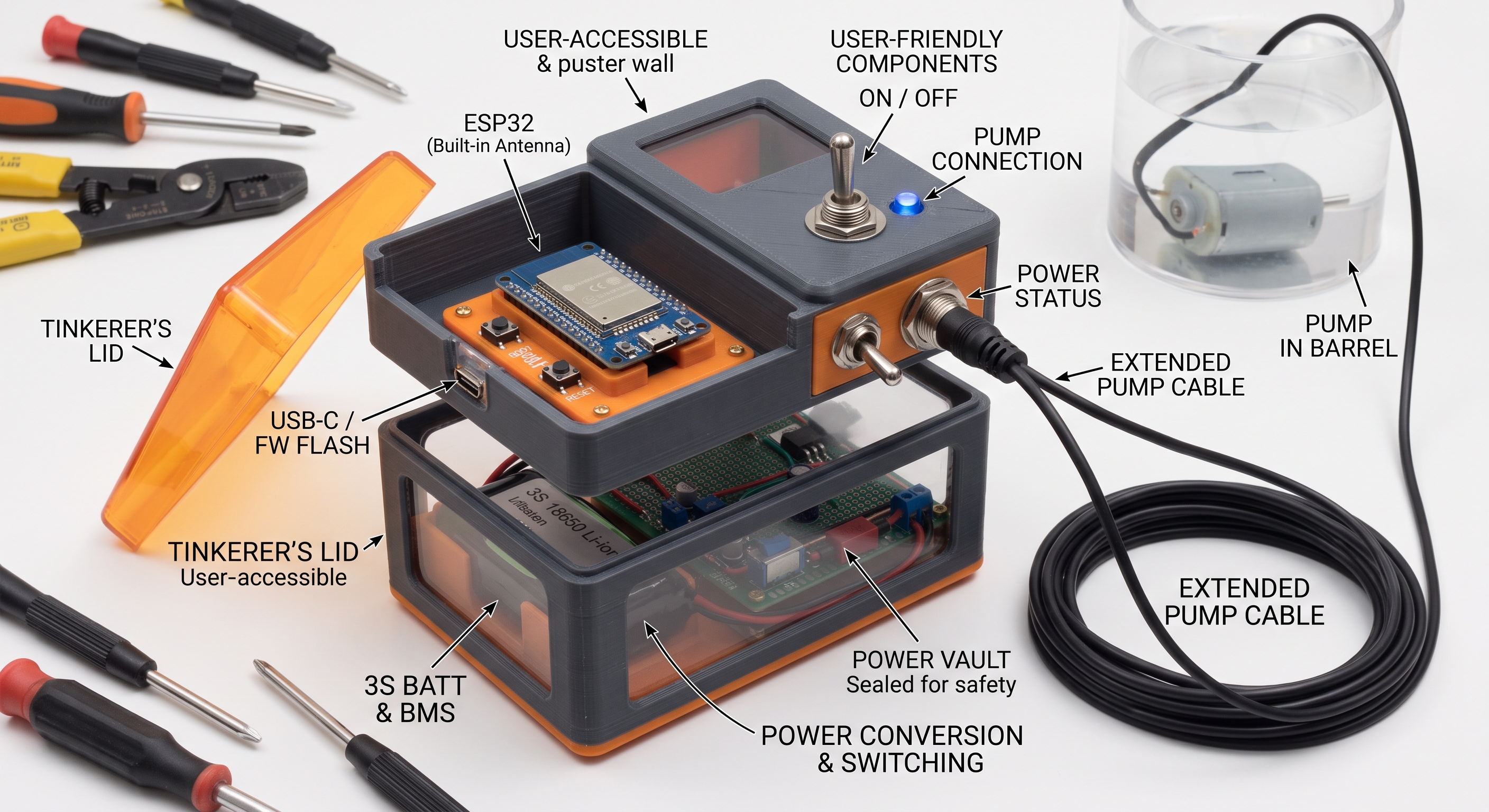
Adding Solar
The main difference comes down to how each board manages solar power conversion, efficiency, and battery configuration:
| Feature | TP4056 (Linear Charger) | MPPT Charger (e.g., CN3791 / MP2467) |
|---|---|---|
| Charging Method | Linear regulation | High-efficiency switch-mode (Buck/Boost) |
| Solar Voltage Tracking | None; pulls solar panel voltage down to battery level | Actively matches the panel’s Maximum Power Point ($V_{mp}$) |
| Battery Compatibility | Single cell only (1S / 3.7V–4.2V) | Available for 1S, 2S, 3S, 4S multi-cell packs |
| Efficiency in Sub-optimal Light | Low (~30%–60% of panel rating is wasted as heat) | High (typically 85%–95% overall energy harvest) |
| Input Voltage Range | Narrow (typically 4.5V–6V max) | Wide (often supports 6V to 28V+ panels) |
Voltage Mismatch & Wasted Power: A standard 12V or 18V solar panel connected to a standard TP4056 will either burn it out due to high input voltage or force the panel to collapse down to 4.2V, throwing away more than half of the usable wattage as heat.
Multi-Cell Packs: A standard TP4056 can only charge a 1S (single 3.7V cell) setup. To charge a 3S (12.6V) pack like the one in your schematic directly from solar, an MPPT step-up/step-down multi-cell board is required to deliver the proper voltage and CC/CV profile.
Cost vs. Performance: The
TP4056works reliably for small 5V USB panels and single-cell projects, but an MPPT board is necessary to safely and efficiently step solar voltages up or down for a 3S pack.
| Feature | MPPT (Maximum Power Point Tracking) | PWM (Pulse Width Modulation) |
|---|---|---|
| Operating Principle | High-frequency DC-to-DC converter that dynamically adjusts load to match peak panel wattage. | Rapid on/off switch that pulls panel voltage directly down to the battery’s voltage level. |
| Conversion Efficiency | 90% – 99% | 70% – 80% (drops lower in cold or low-light conditions) |
| Voltage Flexibility | High input voltage support (e.g., 50V–150V+ panel arrays into a 12V/24V battery). | Panel nominal voltage must strictly match battery voltage (e.g., 18V $V_{mp}$ panel for a 12V battery). |
| System Scale | Best for medium-to-large setups (>200W), multi-panel arrays, and residential/commercial solar. | Best for small systems (<150W–200W), single-panel DIY, RVs, and trickle-charging. |
| Cost | Significantly higher ($40 to $500+) | Very low ($10 to $30) |
MPPT vs PWM 🚀
MPPT Pros & Cons
Pros:
- Maximum Energy Harvest: Captures up to 30% more energy than PWM, especially in cloudy, low-light, or cold weather.
- Higher Panel Voltage Allowed: Lets you wire panels in series at high DC voltage, allowing for longer cable runs with thinner, cheaper wiring and lower transmission losses.
- System Expandability: Easy to add more panels to an existing array without replacing the battery bank voltage configuration.
Cons:
- Higher Price Tag: Complex internal circuitry and microcontrollers make it 3x–5x more expensive than PWM.
- Size and Weight: Larger enclosures, bulkier inductors, and heavier heatsinks.
- Marginal Value on Tiny Setups: Overkill for small (<100W) installations where the extra power gained doesn’t justify the controller’s cost.
PWM Pros & Cons
Pros:
- Extremely Cheap: Lowest cost-per-unit solution for basic solar installations.
- Simple & Reliable: Fewer active electronic components result in low standby draw and solid long-term durability.
- Compact Footprint: Lightweight and easy to fit into tight enclosure boxes.
Cons:
- Wasted Capacity: Forces the panel to operate at battery voltage; any excess voltage is simply lost rather than converted to current.
- Strict Voltage Constraints: Cannot step down high array voltages (e.g., cannot use high-voltage grid-tie panels with a 12V battery bank).
- Poor Poor-Weather Performance: Harvest drops sharply when temperatures fall or in overcast lighting conditions.
| Feature | TP4056 | TP5100 | CN3791 | 3S MPPT Charger (e.g., CN3795 / MP2467) |
|---|---|---|---|---|
| Topology | Linear regulator | Switching (Buck converter) | Switching (Buck converter) | Switching (Buck/Boost) |
| Solar MPPT? | No | No (fixed DC input) | Yes (Input voltage tracking) | Yes (Input voltage tracking) |
| Supported Battery | 1S only (4.2V) | 1S or 2S (4.2V / 8.4V) | 1S only (4.2V) | 3S (12.6V) |
| Input Voltage | 4.5V – 5.5V | 5V – 18V | 4.5V – 28V | 15V – 28V+ |
| Max Charge Rate | 1A | Up to 2A | Up to 4A | Typically 2A – 5A+ |
TP5100: A Switching Upgrade, But Not for Solar or 3S
- The Pros: Unlike the linear TP4056, the TP5100 is an efficient buck (step-down) switcher. It handles higher input voltages (up to 18V) without turning excess energy into extreme heat.
- The Limit: It only supports 1S (4.2V) or 2S (8.4V) batteries. It cannot charge a 3S (12.6V) pack. Furthermore, it lacks MPPT circuitry, meaning a cloud passing over a solar panel can cause the input voltage to collapse and stall the charge cycle.
CN3791: Real Solar Tracking, But Built for 1S
- The Pros: The CN3791 has built-in MPPT (specifically constant-voltage tracking) designed for solar panels. It monitors panel voltage so it never drags the panel below its peak output ($V_{mp}$).
- The Limit: The standard CN3791 IC is hardwired for single-cell lithium (1S / 4.2V). Even though it accepts high solar panel voltages (up to 28V), it only outputs 4.2V.
What Your Schematic Actually Needs
Because your circuit uses a 3S pack (~12.6V full charge), neither the standard TP5100 nor the CN3791 can charge it.
To charge that 3S pack from solar, look for:
- CN3795 or CN3722: The multi-cell siblings of the CN3791, designed specifically for adjustable multi-cell lithium packs (including 3S and 4S) with MPPT.
- Synchronous Buck-Boost MPPT modules: Modules using chips like the LT8490 or SC8815, which can take an 18V solar panel and safely step it down to 12.6V CC/CV for your BMS.
The primary recommended board is a Synchronous Switching Boost (Step-Up) CC/CV Charger, not a standard PWM or true MPPT tracker.
| Feature | Recommended 5V-to-3S Board (e.g., SD35XX / IP2326) | Standard Solar PWM | Solar MPPT Boost (e.g., SC8815 / LT8490) |
|---|---|---|---|
| Topology | Switching Boost (DC-DC Step-Up) | Direct Pulse Switch (Step-Down only) | Synchronous Buck-Boost with dynamic tracking |
| Can it step 5V up to 12.6V? | Yes | No (PWM can only pass through or drop voltage) | Yes |
| Tracking Method | Fixed input adaptive current limiting | None | Dynamic curve sweep ($V_{mp}$ tracking) |
| Cost | ~$2 to $5 | ~$10 to $20 | ~$25 to $60+ |
Why It Is Not Traditional PWM
A standard PWM solar controller requires the solar panel’s voltage to be higher than the battery pack (e.g., an 18V panel for a 12V battery).
Because your panel outputs only 5V and the 3S pack reaches 12.6V, a PWM controller cannot work—it cannot step voltage up.
Why It Is Not Fully “True MPPT”
Budget 5V-to-3S boost charger boards use switching regulators with adaptive input voltage regulation, not true continuous MPPT tracking.
When a cloud passes over and the 5V panel begins to sag, the chip throttles back charging current to stop the panel from completely collapsing to 0V.
While technically “pseudo-MPPT” or input-voltage limiting, it delivers roughly 85%–90% efficiency without the high cost and complexity of a full MPPT tracking stage.
That works cleanly with the recommended boost charger.
In that setup, the 5V panel slowly charges the 18650 pack, and the 18650 pack supplies the high current bursts for the pump.
How the Energy Flow Operates
Charging Phase (Continuous & Slow):
Sun hits the 5V panel $\rightarrow$ 5V-to-3S boost charger steps 5V up to 12.6V $\rightarrow$ feeds current through
BMS P+andBMS P-$\rightarrow$ BMS charges and balances the three 18650 cells.Discharge Phase (On-Demand & Fast):
When ESP32 GPIO23 turns ON the MOSFET, the pump draws its full ~1.7A (20W) directly from the 3S battery pack via
BMS P+, completely bypassing the solar charger.
SelfHosted IoT Tools
OpenHaB, HA, Node-Red and ESPhome…
Yea, check https://esphome.io if you like ESP32 boards!
HA
There has been few releases since the last time:
Including the releases of the MCP integrations:
#git clone https://github.com/JAlcocerT/Home-Lab
#cd ~/Home-Lab/home-assistant
#sudo docker compose up -d

##cd ~/Home-Lab
#git pull
#sudo docker compose -f ./z-homelab-setup/evolution/2601_docker-compose.yml up -d home-assistant

docker ps -a | grep -i home-assistant
#docker stats home-assistantCustom IoT Tools
But lately, I just made my own DIY IoT platform around MQTT and zigbee:
cd ./poc/iot-dashboardConclusions
After writing about electronics and the electro-magnetic foundations, this post was the clear next step.
I made another tech talk around the DIY IoT Dashboard that integrates with Zigbee
cd ./poc/iot-dashboard
#docker system prune -a --volumes
How much deflation is enough for you to start doing?
Whatever.
Save you effort or make money?
Deal:
 Consulting Services
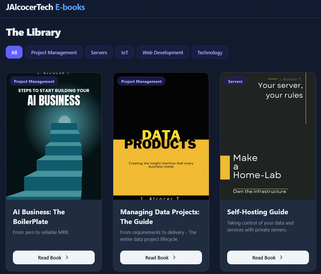
 DIY via ebooks
If anything:
flowchart LR
%% --- Styles ---
classDef free fill:#E8F5E9,stroke:#2E7D32,stroke-width:2px,color:#1B5E20;
classDef low fill:#FFF9C4,stroke:#FBC02D,stroke-width:2px,color:#FBC02D;
classDef mid fill:#FFE0B2,stroke:#F57C00,stroke-width:2px,color:#F57C00;
classDef high fill:#FFCDD2,stroke:#C62828,stroke-width:2px,color:#C62828;
classDef bridge fill:#E3F2FD,stroke:#1565C0,stroke-width:3px,color:#0D47A1;
%% --- Nodes ---
L0("Free Content
( DIY = $0)"):::free
L1("Web Audits 🛡️
(Reveals Problem )"):::free
L11("Tech Blog/Youtube"):::free
L12("ebooks"):::free
L13("mbsd framework OSS"):::free
L14("OSS guides"):::free
L3("Done With You
(Trade $$ for knowledge)"):::mid
L4("Done For You
(Trade $$$ for outcomes)"):::high
L44("GenBI
Shopify PoC"):::bridge
L45("Real Estate
Funnel Bot"):::bridge
L46("Energy Solutions
HVAC"):::bridge
L47("IoT Solutions
Crops"):::bridge
L48("Weddings
Photo QR"):::bridge
%% --- Connections ---
L0 --> L1
L1 --> L3
L12 --> L3
L13 -->|MultiBodySystemsDynamicscom| L3
L14 -->|FOSS Engineer| L3
L0 --> L11
L0 --> L12
L0 --> L13
L0 --> L14
L3 --> L4
L4 -->|Productized Service| L44
L4 -->|Productized Service| L45
L4 -->|Productized Service| L46
L4 -->|Productized Service| L47
L4 -->|Productized Service| L48 Consulting Services
 DIY via ebooks
HomeLab Updates 0826
What else am I running since last month?
sudo docker compose -f 2604_docker-compose.yml up -d uptime....pihole nextcloud ncdb.......uptimekuma pocketbase termix lunalytics...littlyx jellyfinNeeded a cool .md compatible way to keep my daily notes for when im not working with my laptop…
LogSeq vs SilverBullet 🚀
Logseq Web is the wrong model for your specific setup.
If you want to use Logseq from another laptop and have notes write into the repo on your home machine, that won’t happen automatically.
Logseq Web in the browser writes to a folder the browser can access on that same laptop, not to a remote folder on your home server.
So the practical split is:
Good fit
- Using Logseq on a machine that has the notes folder locally
- Or using Logseq on each laptop with its own local clone of the repo
- Then syncing via git, Syncthing, etc.
Poor fit
- Opening Logseq Web from a work laptop and expecting it to write directly into /home/jalcocert/my-logseq-notes on another machine
If your goal is simply “capture daily notes from anywhere and keep them in this repo,” then Logseq is only a good fit if you use it with local storage + sync.
After trying logseq and silverbullet, i went with:
But im considering to build a PWA with optional signin to write
mdto Forgejo or directly to my homelab
I needed to fix nextcloud after my x300 restarted:
sudo mount /mnt/data1tb
sudo systemctl daemon-reload
sudo docker restart nextcloud nextclouddb
#docker exec nextcloud php /var/www/html/occ status

docker exec nextcloud php /var/www/html/occ config:system:get trusted_domains
docker exec nextcloud-sync php /var/www/html/occ config:system:get trusted_domains
You need some clean up?
#ncdu /
uv cache clean
# docker stop dawarich_app dawarich_sidekiq dawarich_db dawarich_redis
docker rm dawarich_app dawarich_sidekiq dawarich_db dawarich_redis

docker volume rm \
  dawarich_dawarich_shared \
  dawarich_dawarich_public \
  dawarich_dawarich_storage \
  dawarich_dawarich_watched \
  dawarich_dawarich_db_data \
  velxio_arduino-libs
#docker image rm ghcr.io/opengeos/geolibre:latest

docker builder pruneI removed the services for my ebooks and consulting subdomains.
They are now…static!
Consulting ServicesDIY via ebooksYou have one IoT basics ebook waiting :)
FAQ
HomeLab Tools I cant live w/o
For the CLI:
lazydocker
#docker ps --filter "status=running"
#docker ps -a --filter "name=home-assistant"
#docker stats home-assistant

glances #htop btop
#sudo snap install ghostty --classic
herdr #tmux #ghostty
Interesting Sensors
https://sonoff.tech/en-pl/products/sonoff-snzb-02d-zigbee-lcd-smart-temperature-humidity-sensor
Zigbee
If you have been playing with IoT and some home devices, you will come to know Zigbee.
Zigbee devices cannot speak MQTT directly out of the box.
MQTT is an IP-based protocol (it requires Wi-Fi, Ethernet, and a TCP/IP network stack), whereas Zigbee is a low-power RF radio protocol (IEEE 802.15.4) that does not understand Wi-Fi or IP addresses.
Zigbee, Tuya, Sonof…? 📌
To bridge the gap between the two technologies, you need an intermediary coordinator.
A USB Zigbee Coordinator: A ~$15–$25 USB dongle (such as the Sonoff ZBDongle-E or SLZB-06) plugged into whatever computer/server hosts your MQTT broker.
Zigbee2MQTT (Z2M): A lightweight open-source service that pairs with the dongle, handles the device drivers locally, and outputs pure MQTT.
- https://www.zigbee2mqtt.io/supported-devices/
- https://fossengineer.com/zigbee2mqtt-self-hosted-zigbee-bridge/
They are often mentioned in the same breath because they dominate the budget smart home market, but they represent three distinct things: a protocol, an IoT platform, and a hardware brand.
The Three Entities Defined
| Name | What It Actually Is | Primary Role |
|---|---|---|
| Zigbee | An open wireless standard/protocol (like Wi-Fi or Bluetooth) | The low-power radio language devices use to talk to each other. |
| Tuya | A massive IoT platform / white-label software provider | Supplies turnkey chips, firmware, and cloud backends to hundreds of OEM factories (Moes, Zemismart, generic brands). |
| Sonoff | A specific hardware manufacturer (brand owned by ITEAD) | Builds smart home hardware (Wi-Fi and Zigbee relays, sensors, dongles, and switches). |
How They Intersect
                    ┌── Zigbee Protocol ──► (Used by both Sonoff & Tuya hardware)
                    │
Smart Home Landscape ┼── Tuya Ecosystem   ──► (White-label firmware/cloud across 1,000s of brands)
                    │
└── Sonoff (ITEAD) ──► (A single manufacturer with its own eWeLink app)- Zigbee is the common language: Both Sonoff and Tuya make devices that speak the Zigbee protocol instead of Wi-Fi.
- They make competing ecosystems:
- A Tuya Zigbee device connects by default to a Tuya hub (Smart Life app).
- A Sonoff Zigbee device connects by default to a Sonoff hub (eWeLink app).
standard Zigbee broadcasts on the same 2.4 GHz frequency band as Wi-Fi and Bluetooth, it uses a different physical layer format (IEEE 802.15.4 instead of 802.11 or BLE).
A smartphone or standard router cannot decode its beacon signals.
- Open-source bridges unite them: Tools like Zigbee2MQTT ignore both the Tuya and Sonoff proprietary clouds. As long as the device speaks Zigbee, a single open USB dongle (often made by Sonoff) can control Tuya sensors, Sonoff switches, Philips Hue bulbs, and IKEA blinds on one unified MQTT network.
- Zigbee is the radio layer.
- Tuya is the turnkey software/chip ecosystem behind most generic smart gadgets on AliExpress/Amazon.
- Sonoff is a hardware vendor famous in the DIY community for making hacker-friendly, flashable ESP8266/ESP32 devices and cheap Zigbee hardware.
Wi-Fi is high-bandwidth, high-power, and connects devices directly to your router over standard TCP/IP.
Zigbee is ultra-low-power, low-bandwidth, and creates a local mesh network designed specifically for tiny sensor packets and battery-operated hardware.
Core Differences: Zigbee vs. Wi-Fi
| Feature | Wi-Fi (802.11) | Zigbee (802.15.4) |
|---|---|---|
| Topology | Star: Every device connects directly to your main router. | Mesh: Mains-powered devices relay signals to extend range and self-heal. |
| Power Consumption | High: Drains coin/small batteries in days to weeks. | Extremely Low: Battery devices sleep and last 1–3+ years on a coin cell. |
| Addressing / Network | Full IP stack (MAC, IP, Subnet, DNS, TCP/UDP). | 16-bit short address inside a local PAN (Personal Area Network). No IP. |
| Bandwidth | High (54 Mbps to 1+ Gbps) — handles video, web, streaming. | Low (~250 kbps) — sends only tiny command and state payloads. |
| Router Load | 30–50+ Wi-Fi smart devices can congest standard home routers. | Handles 100+ devices easily via a dedicated USB coordinator. |
| Native Protocols | HTTP, WebSockets, standard TCP MQTT clients. | Zigbee Cluster Library (ZCL) byte commands. |
How Zigbee2MQTT (Z2M) Works
Zigbee devices don’t have IP addresses and can’t run an MQTT client.
Zigbee2MQTT acts as a software/hardware translator that bridges the physical Zigbee radio network to your local IP network and MQTT broker.
 [ Battery Sensor / Blind ]
             │
             │ (Raw Zigbee RF Packets: IEEE 802.15.4)
             ▼
   [ USB Coordinator ]  (e.g., Sonoff ZBDongle-E / Texas Instruments chip)
             │
             │ (Serial / UART over USB)
             ▼
   [ Zigbee2MQTT Service ] (Runs on Raspberry Pi / Home Server)
             │
             │ (JSON payloads over TCP/IP)
             ▼
   [ MQTT Broker (Mosquitto) ] ◄──► [ ESP32 / Home Assistant / Custom Scripts ]
IoT BoM to get started
Getting started?
Get some of these:
- ESP32 or a PicoW ~5/10$
- DHT11/22 ~1/5$
- MLX90614 infrared sensors ~20$
- TP4056 - to control the battery charge ~10$ with the shield
For your automatic watering setup:
Watering what?
Oh, yep, i planted some tomatoes and thats why this all started.
- Pump with a BLDC 12v 30W for ~20$ or smaller 19w for 15$
- A battery: I got a bluetti for 200$, but i was considering a Pb battery
Other learnings
Using a Multimeter / ClampMeter: from continuity tests / resistance measuring, to wall voltage readings
Pumps also go around P/Q:
price/quantityPower, Flow and height, Best Efficiency Point (BEP)…For the Mosfet i used, the 2nd pin (GDS), the DRAIN, is connected to its top metal plate
The Tech Talk
The initial draft of the talk is here.
But as the prior one, this tech talk ppt will be placed somewhere: https://consulting.jalcocertech.com/presentations/techtalk-from-iot-to-big-data-engineering/ppt
#cd ./poc/iot-dashboard
#git clone https://github.com/JAlcocerT/selfhosted-landing
cd ./selfhosted-landing/y2026-tech-talks/5-iot-sensors-to-actuators