[IoT] Sensors x PCB x Gerber
Tl;DR
Isnt it time to build something real?
Intro
- WHY Im writting this post: bc I need a recap and all the BoM that Id wish to have found years back to get started with IoT
- WHAT Ive learnt with it: Ive ended up understanding why Mosfet GDS controlled with 3.3v is ok for my smaller pump, but not for the 20w one, also sent my first pcb for manufacturing
Sensors Ive tried
DHT11 and DHT22
These 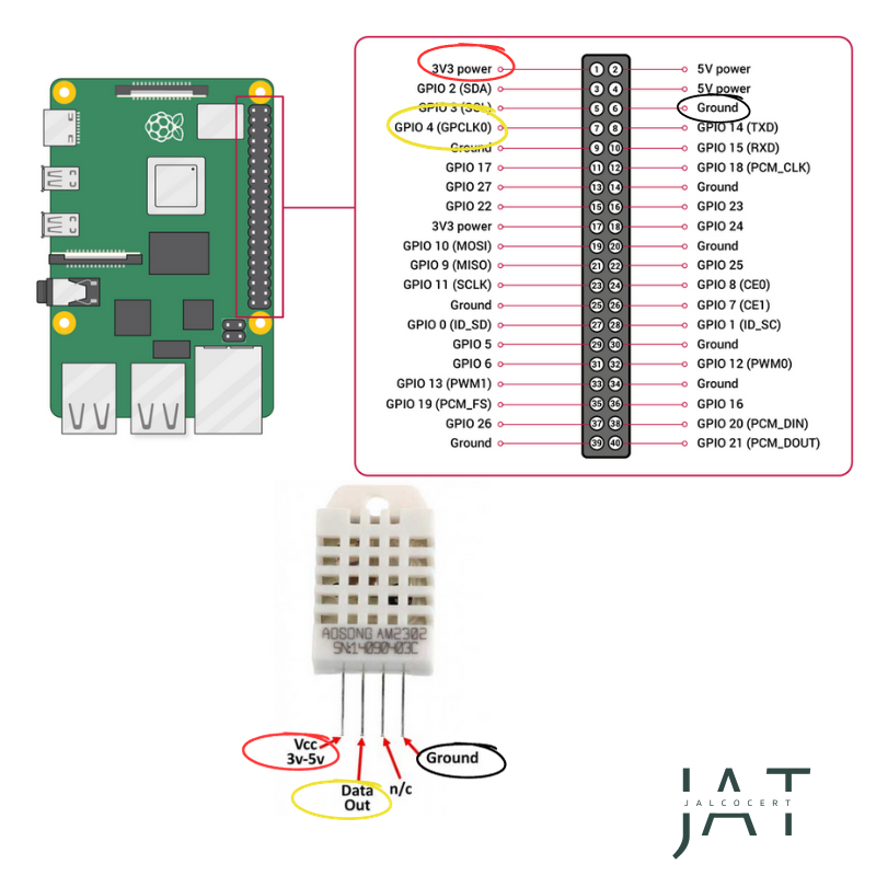 and if you are getting started they are perfect.
sqlite3 -header -column /home/jalcocert/poc/iot-rpi-dht-insulation/ingester/data/readings.sqlite \
  "SELECT COUNT(*), MAX(received_at) FROM readings;"
MLX
This sensor will be helpful to test insulation and build your energy solutions as service offering
The MLX90614 sensor will get you ambient temp and IR temp of an object
- With the Pi4 was kinda simple:
pinout #this assumes that the usb and eth port are looking down, so 5V is top right
i2cdetect -y 1- With the combo ESP32 + MLX90614 also works as seen recently
This guy made it work with a bluetooth setup
Sensors
MLX90614 GY-906 - IR
The MLX90614 GY-906 is an infrared (IR) temperature sensor module commonly used for non-contact temperature measurements.
It’s also known as a pyrometer or non-contact thermometer.
This sensor is produced by Melexis and can measure the temperature of an object without making physical contact with it, which makes it useful in various applications.
More about the MLX90614
Working Principle: The sensor measures the infrared radiation emitted by an object to determine its temperature.
All objects emit thermal radiation based on their temperature, and this radiation falls within the infrared spectrum.
The sensor detects this radiation and converts it into an electrical signal that can be used to calculate the object’s temperature.
Accuracy and Range: The MLX90614 GY-906 sensor can offer a relatively high level of accuracy for non-contact temperature measurements.
It has a wide temperature measurement range, typically spanning from -70°C to 380°C (-94°F to 716°F), depending on the specific model and calibration.
Two Sensors in One: The sensor actually contains two separate sensors within a single package: one to measure the temperature of the object being measured (object temperature) and another to measure the temperature of the sensor itself (ambient temperature).
This dual-sensor setup helps improve accuracy, as it compensates for changes in the sensor’s ambient temperature.
Communication Interface: The MLX90614 GY-906 sensor can communicate with microcontrollers or other devices using the I2C (Inter-Integrated Circuit) communication protocol.
This makes it relatively easy to integrate the sensor into various projects and systems.
It already has a built-in 3.3V voltage stabilizer and pull-up resistors of the I2c bus to be powered by 4.7 kΩ resistors.
We also know that the ranges of measured temperatures are: -40°C…85°C for the ambient temperature and -40°C…380°C for the temperature of the tested object.
The module has a measurement accuracy of 0.5°C for the measurement range To=0°C…60°C ( object temperature ), Ta=0°C…50°C ( surrounding temperature ) with a resolution of 0.2°C.
The largest measurement error we will encounter is ±4°C, but for very high temperatures.
MLX90614 Python, Influx and grafana
https://www.youtube.com/watch?v=CftxT8k0jww&t=5s
Vin to 3.3V - GND to gnd SCL to GPIO3 (SCL) SDA to GPIO2 (SDA)
sudo raspi-config
interfacing options
enable I2C

reboot

i2cdetect -y 1
you should see something different than – in at least one of the buckets.
Install Adafruit-blinka https://pypi.org/project/Adafruit-Blinka/ and also: adafruit-circuitpython-mlx90614 https://pypi.org/project/adafruit-circuitpython-mlx90614/
# This is the code to run the MLX90614 Infrared Thermal Sensor
# You'll need to import the package "Adafruit Blinka"
# You'll need to import the package "adafruit-circuitpython-mlx90614/"
# You'll need to enable i2c on the pi https://pimylifeup.com/raspberry-pi-i2c/
# Reboot after enabling i2C
# Sensor is connected to 3.3V, GND and the i2C pins 3(SDA) and 5(SCL)

import board
import busio as io
import adafruit_mlx90614

from time import sleep

i2c = io.I2C(board.SCL, board.SDA, frequency=100000)
mlx = adafruit_mlx90614.MLX90614(i2c)

ambientTemp = "{:.2f}".format(mlx.ambient_temperature)
targetTemp = "{:.2f}".format(mlx.object_temperature)

sleep(1)

print("Ambient Temperature:", ambientTemp, "°C")
print("Target Temperature:", targetTemp,"°C")
to run inside the container
version: '3.8'

services:
  mlx_rpi:
    image: mlx_sensor_app_influxdb
    privileged: true
    command: tail -f /dev/null #keep it running
# Use an official Python runtime as the base image
FROM python:3.8-slim
# Set the working directory in the container
WORKDIR /app
# Install system-level dependencies
RUN apt-get update && \
apt-get install -y python3-dev python3-pip && \
python3 -m pip install --upgrade pip setuptools wheel
# Copy the local code to the container
COPY mlx.py /app/
# Install additional dependencies
RUN pip install board adafruit-circuitpython-mlx90614 Adafruit-Blinka RPi.GPIO influxdb
# Run the Python script
CMD ["python", "mlx.py"]When saved, just run:
docker build -t mlx_sensor_app_influxdb .version: '3.8'
services:
my_python_dev_container:
image: mlx_sensor_app_influxdb #python:3.10
privileged: true
command: tail -f /dev/null #keep it runningI have tagged and uploaded it to my DockerHub so that it works with InfluxDB:
docker tag mlx_sensor_to_influxdb docker.io/fossengineer/iot:mlx_sensor_to_influxdb
docker push docker.io/fossengineer/iot:mlx_sensor_to_influxdb
Check it at https://hub.docker.com/repository/docker/fossengineer/iot/general
Try that it works with:
import board
import busio as io
import adafruit_mlx90614
from influxdb import InfluxDBClient
from time import sleep, strftime

i2c = io.I2C(board.SCL, board.SDA, frequency=100000)
mlx = adafruit_mlx90614.MLX90614(i2c)

# Configure InfluxDB connection
influx_client = InfluxDBClient(host='influxdb', port=8086)

# Try to create the database, or use it if it already exists
database_name = 'sensor_data'
existing_databases = influx_client.get_list_database()

if {'name': database_name} not in existing_databases:
    influx_client.create_database(database_name)
    print(f"Database '{database_name}' created.")

influx_client.switch_database(database_name)

while True:
    ambientTemp = mlx.ambient_temperature
    targetTemp = mlx.object_temperature

    if ambientTemp is not None and targetTemp is not None:
        data = [
            {
                "measurement": "mlx_sensor",
                "tags": {},
                "time": strftime('%Y-%m-%dT%H:%M:%SZ'),
                "fields": {
                    "ambient_temperature": ambientTemp,
                    "target_temperature": targetTemp
                }
            }
        ]
        influx_client.write_points(data)
        print("Ambient Temperature:", ambientTemp, "°C")
        print("Target Temperature:", targetTemp,"°C")
        print("Data sent to InfluxDB")
    else:
        print("Sensor failure. Check wiring.")

sleep(1)version: '3'
services:
mlx_sensor:
image: mlx_sensor_to_influxdb
container_name: mlx_sensor_app
privileged: true
#command: tail -f /dev/null #keep it running for testing
dns:
- 8.8.8.8
- 8.8.4.4
depends_on:
- influxdb
influxdb:
image: influxdb:1.8 #for arm32
container_name: influxdb
ports:
- "8086:8086"
volumes:
- influxdb_data:/var/lib/influxdb
environment:
- INFLUXDB_DB=sensor_data
- INFLUXDB_ADMIN_USER=admin
- INFLUXDB_ADMIN_PASSWORD=mysecretpassword
grafana:
image: grafana/grafana:9.5.7 #was using this one instead of latest for stability
container_name: grafana3
ports:
- "3000:3000"
depends_on:
- influxdb
volumes:
- grafana_data:/var/lib/grafana # Add this line to specify the volume
dns:
- 8.8.8.8
- 8.8.4.4
volumes:
influxdb_data:
grafana_data: # Define the volume for Grafanaimport board
import busio as io
import adafruit_mlx90614
from influxdb import InfluxDBClient
from time import sleep, strftime
import os # Import the os module
i2c = io.I2C(board.SCL, board.SDA, frequency=100000)
mlx = adafruit_mlx90614.MLX90614(i2c)
# Get values from environment variables (with default values if not set)
INFLUX_HOST = os.environ.get('INFLUX_HOST', 'influxdb')
INFLUX_PORT = int(os.environ.get('INFLUX_PORT', 8086))
DATABASE_NAME = os.environ.get('DATABASE_NAME', 'sensor_data')
MEASUREMENT = os.environ.get('MEASUREMENT', 'mlx_sensor')
SLEEP_TIME = int(os.environ.get('SLEEP_TIME', 1))
# Configure InfluxDB connection
influx_client = InfluxDBClient(host=INFLUX_HOST, port=INFLUX_PORT)
# Try to create the database, or use it if it already exists
existing_databases = influx_client.get_list_database()
if {'name': DATABASE_NAME} not in existing_databases:
influx_client.create_database(DATABASE_NAME)
print(f"Database '{DATABASE_NAME}' created.")
influx_client.switch_database(DATABASE_NAME)
while True:
ambientTemp = mlx.ambient_temperature
targetTemp = mlx.object_temperature
if ambientTemp is not None and targetTemp is not None:
data = [
{
"measurement": MEASUREMENT,
"tags": {},
"time": strftime('%Y-%m-%dT%H:%M:%SZ'),
"fields": {
"ambient_temperature": ambientTemp,
"target_temperature": targetTemp
}
}
]
influx_client.write_points(data)
print("Ambient Temperature:", ambientTemp, "°C")
print("Target Temperature:", targetTemp,"°C")
print("Data sent to InfluxDB")
else:
print("Sensor failure. Check wiring.")
sleep(SLEEP_TIME)Locally you will do:
version: '3'
services:
  mlx_sensor:
    image: mlx_sensor_to_influxdb
    container_name: mlx_sensor_app
    privileged: true
    #command: tail -f /dev/null #keep it running for testing
    dns:
      - 8.8.8.8
      - 8.8.4.4
    depends_on:
      - influxdb
    environment:
      - INFLUX_HOST=reisikei.duckdns.org
      - INFLUX_PORT=8086
      - DATABASE_NAME=sensor_data
      - MEASUREMENT=mlx_sensor_sec
      - SLEEP_TIME=1

  influxdb:
    image: influxdb:1.8 #for arm32
    container_name: influxdb
    ports:
      - "8086:8086"
    volumes:
      - influxdb_data:/var/lib/influxdb
    environment:
      - INFLUXDB_DB=sensor_data
      - INFLUXDB_ADMIN_USER=admin
      - INFLUXDB_ADMIN_PASSWORD=mysecretpassword


  grafana:
    image: grafana/grafana:9.5.7 #was using this one instead of latest for stability
    container_name: grafana3
    ports:
      - "3000:3000"
    depends_on:
      - influxdb
    volumes:
      - grafana_data:/var/lib/grafana  # Add this line to specify the volume
    dns:
      - 8.8.8.8
      - 8.8.4.4

volumes:
  influxdb_data:
  grafana_data:  # Define the volume for Grafana
Grafana can connect to:
http://influxdb:8086or tohttp://yoursubdomain.duckdns.org:8086if you included the DNS in the stack
Go to the Influx container and then:
Influx
USE sensor_data
show measurements
SELECT * FROM mlx_sensor #this is the measurement where we are pushing this data
I tested this with DuckDNS: http://reisipi.duckdns.org pinting to http://192.168.3.101:8086
and using influxdb in the cloud
https://www.influxdata.com/influxdb-cloud-pricing/
USD 0.002 /mebibyte
versus GCP E2 small That’s about $0.02 hourly
version: '3'
services:
  mlx_sensor:
    image: mlx_sensor_app_influxdb
    container_name: mlx_sensor_app
    privileged: true
    dns:
      - 8.8.8.8
      - 8.8.4.4
    # depends_on: #make sure influxdb its ready
    #   - influxdb
    environment:
      - INFLUX_HOST=reisikei.duckdns.org
      - INFLUX_PORT=8086
      - DATABASE_NAME=sensor_data
      - MEASUREMENT=mlx_sensor_sec
      - SLEEP_TIME=1
    #command: tail -f /dev/null #keep it running for testing
    restart: unless-stopped

  grafana:
    image: grafana/grafana:9.5.7 #was using this one instead of latest for stability
    container_name: grafana3
    ports:
      - "3000:3000"
    depends_on:
      - influxdb
    volumes:
      - grafana_data:/var/lib/grafana  # Add this line to specify the volume
    dns:
      - 8.8.8.8
      - 8.8.4.4
    restart: unless-stopped


volumes:
  grafana_data:  # Define the volume for Grafana
in GCP i was running portainer, influxdb and duckdns remember that you will need a firewall rule for the TCP port 8086 (influxDB)
DS18B20
I also got this one working with the Pi4 some time ago
-55 to 125C
data to D13
a
The movement sensor
b
Soil humidity!
Conclusion
Home Assistant is great
And you have some products built around it: https://works-with.home-assistant.io/certified-products/
But hey, are we still drag n dropping?
Ship a DIY Custom HA
cd ./poc/iot-dashboardInteresting YT channels for IoT and sensors.
Tom Stanton - https://www.youtube.com/watch?v=6gchoHrsCp4 ~DIY
Also these: https://www.youtube.com/@homeassistant_facil/videos - https://www.youtube.com/@homeassistant_facil/videos
FAQ
Arduino x QCOM
Recently, arduino has been bought by QCOM.
Historically, Arduino has maintained a strong open-source philosophy for both its hardware and software.
The schematics, PCB designs, and core firmware for Arduino boards like the Uno, Mega, and others have been openly available, allowing manufacturers and hobbyists to create compatible clones or customize designs.
The Arduino Integrated Development Environment (IDE) and associated libraries are also open-source, supporting collaborative development and community-driven improvements.
https://github.com/855princekumar/sense-hive
Motivation for Arduino
Arduino + Acelerometer data in real time?
Wait.
People are doing… what?
Combining Blender + Arduino + Real Time Accelerometer Data: https://pabramsor.com/blender-and-arduino-accelerometer/
I have pending a post about Blender.
But what this guy created on that article is simply fantastic.
See in real time where the arduino is moving rendered into blender https://github.com/Bardo91
Impressive that this was done back in 2011
What?!
We could use one of these for trackdays / karting and so on?
There is also: PolanDuino
Lora
BoM
BMS board
a bare TP4056—it is an 18650 Battery Shield V3, which is a complete, self-contained single-cell power bank system.
Why You Didn’t Need an Extra BMS for That Setup On the bottom of that board sits an all-in-one power management IC (usually an IP5306 or a TP4056 paired with an onboard boost controller and protection chips). It already provides:
Over-discharge protection: Automatically shuts off the 5V and 3V rails when the 18650 cell drops around ~2.9V–3.0V.
Over-charge protection: Stops charging from the Micro-USB port once the cell reaches 4.2V.
Over-current and short-circuit protection.
Voltage conversion: Boosts the single cell’s ~3.7V up to a regulated 5V (USB port and pins) and steps it to 3V pins.
Because that shield already contains a full 1S management and protection circuit, you did not need a separate BMS for it.
that works fine for powering the ESP32 alone, but there are three crucial details to ensure it stays reliable:
- Solar Panel Voltage Limit (5V to 6V Max)
The charging input chip on this shield accepts 5V to 8V maximum.
Use a 5V or 6V (nominal) solar panel.
Do not plug a standard 12V or 18V solar panel directly into this board’s Micro-USB input, or the input charging IC (marked U2) will instantly burn out.
- Pass-Through Charging Behavior
This shield supports simultaneous charging and discharging. However, the charging circuit only draws about 500mA (0.5A) from the input port.
While an active ESP32 uses ~150–250mA, brief Wi-Fi transmissions spike to ~500mA. On cloudy days or low-sun conditions, the incoming solar energy might only cover the ESP32’s consumption without adding charge to the battery. Utilizing ESP32 Deep Sleep between readings or transmissions will keep the battery healthy and charging properly.
- The Slide Switch Only Controls the Big USB-A Port
The slide switch on the side disconnects only the large USB-A socket.
The solder pins along the edge labeled 5V and 3V stay powered on permanently, regardless of that switch’s position. If you want to shut the ESP32 off manually while using those pins, you will need an external inline switch.
Perfboards / Protoboards (Permanent & Soldered)
Once your circuit works on a breadboard, you solder components onto these boards to create a permanent, vibration-resistant device.
Green Double-Sided Board (Bottom-Left):
Made of FR-4 (fiberglass) with plated through-holes (copper lines both sides and passes through the barrel).
Highly durable, resists heat well (pads won’t peel off easily when soldering), and creates very strong solder joints. This is the best board for your final off-grid pump project.
Brown Single-Sided Board (Bottom-Right, 5×7 cm):
Made of FR-2 (paper-phenolic/Bakelite) with copper pads only on the bottom side.
Cheaper and more brittle. The copper pads can easily lift or tear off if your soldering iron stays on them a second too long.
Breadboards: ~1.0A max (realistically 1.5A for brief spikes). The tiny metal spring clips inside breadboards have relatively high contact resistance. Pushing your pump’s ~2A continuous (and 4A–6A inrush) through a breadboard will cause voltage drops, contact heating, and will eventually melt the plastic tracks. Never route the pump motor’s high-current loop through the breadboard clips.
Perfboards (Soldered): Up to 10A+, depending on the wire you use. The isolated copper donut pads themselves don’t carry continuous current across points—you bridge them with wire. If you solder solid 20 AWG or 22 AWG copper hookup wire (or trimmed component lead legs) directly along the high-current path between the BMS, MOSFET, and pump terminals, it handles 5A–10A easily without heating up.
Current Limits
- Breadboards: ~1.0A max (realistically 1.5A for brief spikes). The tiny metal spring clips inside breadboards have relatively high contact resistance. Pushing your pump’s ~2A continuous (and 4A–6A inrush) through a breadboard will cause voltage drops, contact heating, and will eventually melt the plastic tracks. Never route the pump motor’s high-current loop through the breadboard clips.
- Perfboards (Soldered): Up to 10A+, depending on the wire you use. The isolated copper donut pads themselves don’t carry continuous current across points—you bridge them with wire. If you solder solid 20 AWG or 22 AWG copper hookup wire (or trimmed component lead legs) directly along the high-current path between the BMS, MOSFET, and pump terminals, it handles 5A–10A easily without heating up.
Perfboards vs. Custom KiCad PCBs
A custom PCB ordered from a fabrication house (via KiCad) is significantly better in almost every way, except for delivery time and cost on one-off prototypes.
| Factor | Hand-Soldered Perfboard | Custom KiCad PCB |
|---|---|---|
| Reliability & Strength | High risk of short circuits, messy wiring underneath, joints can snap with vibration. | Clean, vibration-proof, insulated solder mask prevents accidental shorts. |
| Current Handling | Depends entirely on the gauge of hookup wire you manually solder. | You design wide copper traces or copper pours (e.g., 2–3 mm wide) capable of 5A–10A cleanly. |
| Assembly Time | Very slow: requires stripping, bending, point-to-point jumpers, and solder bridging. | Fast: parts drop straight through clearly labeled silkscreen footprints and solder down in minutes. |
| Size & Neatness | Bulky, limited to 2.54 mm grid spacing. | Extremely compact; fits neatly into a tailored 3D-printed enclosure. |
| Cost & Speed | Instant build at your desk; costs pennies. | Takes 3–7 business days to manufacture and ship; costs around $2 to $5 for 5 boards (plus shipping). |
For an off-grid device with a pump that vibrates, building a quick prototype on the green FR-4 perfboard will verify everything works. If you want a rock-solid, weather-sealed device that will run unattended for months or years, designing a small board in KiCad is well worth the effort.
Do you plan to build just one of these units, or are you looking to deploy several?
The switch with the metal lever is a heavy-duty toggle switch (latching, typically rated for 10A–15A). It physically stays in the ON or OFF position and is built to switch high-current power lines directly.
The switches in the compartment box are 12×12 mm tactile push buttons with snap-on colored caps. They are not interchangeable with your toggle switch for main power.
Why the Tactile Buttons Cannot Replace the Toggle Switch Directly
- Momentary, Not Latching: These buttons only make electrical contact while your finger is actively holding them down. The moment you let go, the connection opens and power cuts out.
- Very Low Current Rating: Tactile switches are rated for signal levels—typically 50 mA (0.05A) at 12V. Routing your 3S battery (~12V) or the pump’s ~2A through one of these will weld the tiny internal contacts shut or melt the plastic body almost instantly.
When You Can Use the Colored Buttons
You can use them as logic inputs to the ESP32, but not in the main power path:
- Solder a tactile button between an ESP32 GPIO pin and GND (using the ESP32’s internal pull-up resistor).
- When pressed, the ESP32 detects the button press in software and activates the MOSFET to run the pump for a set duration (e.g., “run for 10 seconds, then shut off”).
If you want a small board-mounted switch to cut the main battery power cleanly, look for a mini latching toggle switch or a high-current slide switch rated for at least 3A to 5A DC.
You are thinking of SPST or SPDT.
Looking at the photo, because it has only two screw terminals on the bottom, it is an SPST switch:
- SPST (Single Pole, Single Throw): A simple ON/OFF switch with 2 terminals. Flip it one way, the circuit is connected (closed); flip it the other, it disconnects (open). This is exactly what you have wired inline to cut main power.
- SPDT (Single Pole, Double Throw): Has 3 terminals. It switches one incoming wire between two different output paths (like selecting between Battery A and Battery B, or an ON-OFF-ON configuration).
The letters break down as:
- Pole: The number of separate circuits the switch controls at once (Single Pole = 1 line).
- Throw: The number of active positions each pole can connect to (Single Throw = 1 path, Double Throw = 2 selectable paths).
IoT bom to get started?
you can get cables with 3a/60w support
ToolBest Household RoleYour Clamp MeterHigh-Current AC Testing Hands-Free. Clamping over a live wire at your breaker panel to see how many Amps an induction hob, oven, heat pump, or EV charger is pulling without breaking the circuit.
UT61E+ Multimeter Precision Probing & Fault Finding. Measuring actual wall voltage, checking micro-currents, tracing broken wires, inspecting capacitors, and bench work (FPV & IoT).
For electronics you will be working a lot with DC.
Beyond the basic inventory with R,C, MOSFETs, Diodes, bread and perf/protoboards…
Good easy replacements for the 20 W / 3S pack: to work instead of the 1N4007 (1A rated)
- SS34 — 3 A, 40 V Schottky; a very good fit
- 1N5822 — 3 A, 40 V Schottky; also good
- 1N5408 — 3 A, 1000 V conventional diode; workable, though Schottky is preferable
You will probably need:
- Get some buck converts to convert DC up to DC down: LM2596 or MP1584EN will do for ~10$/10units
LM2596 or MP1584EN
| Feature | LM2596 (Previous Blue Module) | MP1584EN (Current Green Module) |
|---|---|---|
| Size | Bulky | Very compact |
| Efficiency & Tech | Older (150 kHz switching) | Modern & more efficient (1.5 MHz) |
| Adjustment Dial | Multi-turn pot (easy to dial in precisely) | Single-turn pot (extremely twitchy) |
| Max Input | ~40V | ~28V |
For the LM256 the brass slotted screw on top of the blue trimmer.
Use a precision flathead screwdriver to turn it while your multimeter probes are on OUT+ and OUT-:
- Turn counter-clockwise to decrease the output voltage.
- Turn clockwise to increase it.
Because this is a multi-turn trimmer (typically 25 turns), you often have to rotate it 10 to 15 full turns counter-clockwise before the output voltage starts dropping from the input level.
Once it enters the active range, small turns will make fine adjustments.
DC to DC with XL4015
The XL4015 is a higher-power step-down (buck) converter.
While the LM2596 and MP1584EN max out around 2A to 3A, the XL4015 is built for up to 5A continuous output (with appropriate heatsinking) and frequently comes in variants with adjustable current limiting (constant current / constant voltage).
Here is how the XL4015 slots directly into your comparison:
| Feature | LM2596 (Blue Module) | MP1584EN (Green Module) | XL4015 (Common Red/Blue Module) |
|---|---|---|---|
| Size | Bulky (~43 × 21 mm) | Ultra-compact (~22 × 17 mm) | Largest footprint (~54 × 24 mm to 65 × 36 mm) |
| Max Practical Current | ~1.5A continuous (3A peak with heatsink) | ~1.5A continuous (3A short burst) | 4A continuous, 5A max (with heatsink) |
| Efficiency & Tech | Older bipolar tech, 150 kHz | Modern CMOS, ~1.5 MHz | Modern MOSFET-based, 180 kHz, ~96% peak efficiency |
| Adjustment Dial | Multi-turn pot (CV only) | Single-turn pot (CV only, very twitchy) | Multi-turn pot (often dual pots for both CV and CC) |
| Max Input | ~40V | ~28V | ~36V to 38V (dropout ~1.5V) |
| Current Limiting (CC) | No (voltage regulation only) | No (voltage regulation only) | Yes, on dual-pot models (can charge batteries or drive LEDs) |
Key Practical Differences
Real 4A–5A Muscle: The LM2596 and MP1584EN will thermal-throttle or fail if pushed past 2A for prolonged periods. The XL4015 uses an internal low-$R_{DS(on)}$ power MOSFET instead of an old bipolar transistor, meaning significantly lower heat dissipation at 3A–4A.
True Constant Current (CC / CV): Most common XL4015 boards feature two multi-turn trimmers (and often three onboard LEDs: Constant Current, Constant Voltage, and Fully Charged). This makes the XL4015 a functional, benchtop-style CC/CV charger for lithium packs, lead-acid batteries, or high-power LED strings, whereas the LM2596 and MP1584EN simply shut down or brown out under overcurrent.
Thermal Overhead: Because it is designed to push up to 75W, almost all XL4015 boards ship with or require an aluminum stick-on heatsink over the IC.
If you need tiny physical size, stick with the MP1584EN.
If you need simple 1A–2A step-down with an easy dial, the LM2596 works fine.
If you need higher current (3A–5A), battery charging, or fine-tuned current limiting, use the XL4015.
- For powering: you can make an overkill with a bluetti and a DC connector, or get some 18650 batteries anda
XTAR VC4SLcharger
with a TP4056 for a 1s setup
See how the data has been flowing for a while:
#cd ./poc/iot-rpi-dht-insulation
sqlite3 /home/jalcocert/poc/iot-rpi-dht-insulation/ingester/data/readings.sqlite "
SELECT
  date(received_at) AS day,
  ROUND(AVG(CASE WHEN device = 'esp32' AND metric = 'humidity' THEN value END), 2) AS esp_humidity,
  ROUND(AVG(CASE WHEN device = 'esp32' AND metric = 'temperature' THEN value END), 2) AS esp_temp,
  ROUND(AVG(CASE WHEN device = 'pico' AND metric = 'humidity' THEN value END), 2) AS pico_humidity,
  ROUND(AVG(CASE WHEN device = 'pico' AND metric = 'temperature' THEN value END), 2) AS pico_temp,
  COUNT(*) AS total_readings
FROM readings
WHERE device IN ('esp32', 'pico')
  AND metric IN ('humidity', 'temperature')
GROUP BY day
ORDER BY day;"
or with a BMS for the 3s to avoid them to be used below their operating voltage
Tp4056 vs BMS vs Shield
| Feature / Board | 18650 Battery Shield V3 (Your black board) | Standard TP4056 Module (With protection) | 3S–5S 100A BMS (Your large green board) |
|---|---|---|---|
| Cell Configuration | 1S (1 cell, 3.7V nominal) | 1S (1 cell, 3.7V nominal) | 3S, 4S, or 5S (configurable multi-cell) |
| Output Voltages | Regulated 5V (USB & pins) and 3V pins | Direct battery voltage (~3.0V – 4.2V) | Raw pack voltage (~9.0V – 12.6V in 3S) |
| Max Continuous Current | ~1A – 2A (5V boosted rail) | ~1A – 3A (limited by protection chip) | 60A – 100A |
| Built-in Charging | Yes (Micro-USB / 5V input, ~0.5A charge) | Yes (Micro/Type-C, adjustable up to 1A) | No (Requires external CC/CV 12.6V charger) |
| Primary Use Case | Low-power 5V/3.3V boards (ESP32, Arduino) | 1S DIY power banks, single-cell sensors | Power tools, heavy inverters, 12V motors |
| Pros | • All-in-one (holder, charger, boost, protection) |
• Direct plug-and-play 5V output for ESP32
• Works directly with a 5V solar panel | • Tiny footprint and very cheap
• Extremely low idle parasitic draw
• Easy to integrate into custom enclosures | • Handles massive current & high motor startup spikes
• Active cell balance monitoring across series cells
• Heavy copper pads for thick wiring |
| Cons | • Zero reverse polarity protection (burns instantly)
• Boost circuit wastes ~10–15% efficiency
• Cannot drive 12V loads (like your pump) | • No 5V boost (needs external step-up for 5V)
• Requires separate battery holder / soldering
• Cannot handle 12V loads | • No built-in charger circuit
• High idle standby drain for small projects
• Physical overkill and tricky 3S pin-jumping |
KiCad x Power Stage PCB Design
Coming from this high level overview of the watering design.
Yep, the one that could become a product
Its about time to remove some of the cables at my table
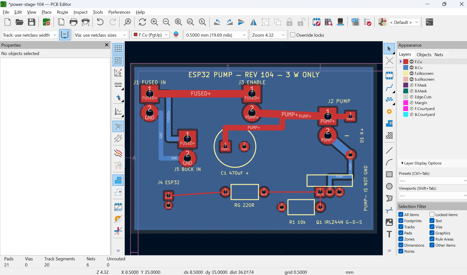
I got a PRD and some instructions / concerns of what i need to get a cleaner power stage prototype for the watering setup:
#choco install kicad
winget install --id KiCad.KiCad --exact --source winget
Placed here all the kicad learnings to generate the gerber files for production
My First PCB
For my first order which ended up being this one
Got to know about these
- Satland
https://www.prototypy.com/t/61,Home - Tecno service
https://tspcb.pl/en/order-inquiry/ - Aisler, JLCPCB / PCBWay…
When ordering bare boards (no assembly required), compress these files into a .zip:
*.GTL / *.GBL (Top and Bottom Copper)
*.GTS / *.GBS (Top and Bottom Solder Mask)
*.GTO / *.GBO (Top and Bottom Silkscreen)
*.GM1 or *.GKO / *-Edge_Cuts.gbr (Board Outline)
*.DRL / *-PTH.drl, *-NPTH.drl (Excellon Drill files)
Standard specs to select in their order forms: 2 Layers, 1.6 mm thickness, FR4, 1 oz (35 µm) copper, HASL lead-free (or ENIG gold), and green mask with white silkscreen.
DRC means Design Rules Check.
KiCad examines the board for problems such as:
- copper tracks too close together
- tracks not connected to pads
- overlapping objects
- copper too close to the board edge
- silkscreen printed over pads
- missing or invalid board outline
A summary of the order, with clarifications and assumptions:
Before submitting, confirmed the uploaded project name is power-stage-104-fabrication-release-r2-2026-09-15.zip and the form shows: PS104-R2-FAB-2026-09-15
- 65 × 45 mm
- 2 layers
- 1.55 mm FR-4 / TG135
- 35 µm copper
- lead-free HASL
- green mask both sides
- front white silkscreen, back without
- routing only
- bare PCB, quantity 3
One board was 45 euros, x3 63 euros, fabrication ~9 working days, in my hands in ~12days
cd ./poc/iot-esp-water/esp32-cpp-mqtt-pump/power-stage-104
#make help
make pcb-104-gerbers
#make pcb-104-open
On the pcb I designed, square pads are pin 1 and circles are pin 2.
For the two-wire power connectors, that happens to mean:
- J1 FUSED IN: square = FUSED+, circle = GND
- J2 PUMP: square = PUMP+, circle = PUMP- — not GND
- J3 ENABLE: square = FUSED+, circle = PUMP+
- J5 BUCK IN: square = FUSED+, circle = GND
- J4 ESP32: square = GPIO23 data/control, circle = GND
Anyways, I tested the pcb for proper continuity of the board before pluging the devices: trying to go from mess to order
Then, soldered:
And…it worked just as I tested with the protoboard:
# #make pub-pulse PULSE_MS=3000
# make pub-status
# make pub-off
docker run --rm --network host eclipse-mosquitto:2 \
  mosquitto_pub -h 192.168.1.2 \
  -t esp32/pump/cmd \
  -m 'pulse:3000'
Electronics Simulations
I was starting here with electronics simulations:
git clone https://github.com/JAlcocerT/electronics-101
#cd ./electronics-101/sample-pyscipe
uv run main.py --only mosfet --scenario compare   # overlay: with vs without diode
If anything: blame these tomatoes for all this
One ESP - Few Sensors
For the MLX90614, it makes the most sense to use the default I2C pins on the ESP32.
While the ESP32 is flexible and allows you to map I2C to almost any pin, using the defaults ensures that almost every library (like the Adafruit one) will work instantly without you having to write extra lines of code to “remap” the pins.
The Best Choice: GPIO 21 and 22
On your 30-pin ESP-WROOM-32, these are labeled as D21 and D22.
| MLX90614 Pin | ESP32 Pin (GPIO) | Label on Board |
|---|---|---|
| SDA (Data) | GPIO 21 | D21 |
| SCL (Clock) | GPIO 22 | D22 |
| VCC | 3V3 | 3.3V |
| GND | GND | GND |
Hardware Support: GPIO 21 and 22 are connected to the ESP32’s internal I2C hardware peripheral. This means the chip handles the communication timing very efficiently.
No “Strapping” Conflicts: Unlike GPIO 15 (which you asked about earlier) or GPIO 0, these pins don’t affect how the ESP32 boots up. You can have the sensor plugged in while you upload code, and it won’t cause any errors.
Library Compatibility: Most code examples you find online for the MLX90614 will assume you are using 21 and 22. It saves you the headache of debugging “Sensor not found” errors.
Can you use the DHT11 and MLX90614 at the same time?
Absolutely!
This is a very common setup.
Since they use different communication methods, they won’t interfere with each other.
Here is your “Master Plan” for wiring both:
| Sensor | Data Pin 1 | Data Pin 2 | Power |
|---|---|---|---|
| DHT11 | D4 (Digital) | None | 3.3V & GND |
| MLX90614 | D21 (SDA) | D22 (SCL) | 3.3V & GND |
Pro Tip: Since the ESP32 only has one
3V3pin and a couple ofGNDpins, you might need a small breadboard to share the power and ground lines between the two sensors.
Most MLX90614 modules (the GY-906 version) come with those 4 pins.
The “extra” pins you might see on the bare sensor (which has 4 pins in a circle) are usually combined or simplified on the PCB module to make it easy to use with microcontrollers like your ESP32.
Understanding the 4 Pins
Here is what each pin does and where it goes on your ESP-WROOM-32:
| Pin Label | Function | ESP32 Connection | Why? |
|---|---|---|---|
| VIN | Voltage In | 3V3 | Powers the sensor. Even if the module can handle 5V, 3.3V is safer for the ESP32. |
| GND | Ground | GND | Completes the electrical circuit. |
| SCL | Serial Clock | D22 (GPIO 22) | This is the “metronome” that keeps the data timing in sync. |
| SDA | Serial Data | D21 (GPIO 21) | This is the actual pipe where the temperature data travels. |
Why 4 pins instead of 3 (like the DHT11)?
The DHT11 uses a custom 1-wire protocol where the “clock” and “data” are mashed into a single wire. It’s simple, but a bit slow and error-prone.
The MLX90614 uses I2C (Inter-Integrated Circuit).
This requires two wires for data communication:
- SDA: Sends the actual bits of temperature data.
- SCL: Sends a steady pulse (the clock) so the ESP32 knows exactly when to “read” each bit on the SDA line.
This makes I2C much faster and more reliable than the DHT11’s method.
Plus, you can actually hook up multiple different I2C sensors to the same two pins (D21 and D22), and the ESP32 can talk to them individually using their “addresses.”
A Quick Tip for a ESP-WROOM-32
Since you are likely using a breadboard now to connect both sensors:
- The “Power Rail”: Connect the ESP32’s 3V3 pin to the red (+) rail on your breadboard and GND to the blue (-) rail.
- Shared Power: Now you can just plug the VIN and GND from both the DHT11 and the MLX90614 into those rails.