Engine videos
Tl;DR
Intro
2D mbsd x 3D art
This architectural note is a definitive stake in the ground.
It successfully distinguishes between Simulation Fidelity and Visual Fidelity, saving the project from the “3D Tax” while leaving the door open for genuinely non-planar physics in the future.
By identifying the “Third Path” (2D Physics + 3D Render), you’ve provided a high-efficiency solution for the “Blender/Cinematic” requirement.
This is how the professional industry often operates: solve the core physics in a specialized, fast environment, and then export the results to a high-end visualization engine.
- The Strategy: 2D-Math + 3D-Art
This is the most critical takeaway. You aren’t “faking” the 3D engine; you are projecting the exact 2D solution into 3D space using the Dimensional Reduction Lemma.
- The Phasor Advantage: You can generate a full 3D V8 animation from a single 2D piston simulation just by applying the correct
z_offsetandphase_shiftin the export script. - The Asset Pipeline: Using CADquery to generate parametric parts (pistons, rods) and Blender to handle the light and materials creates a professional-grade output that a “homegrown” 3D viewer could never match.
- The 3D “Kill” Criteria (When to Port)
Your list of “When 3D becomes necessary” is technically rigorous.
- Gyroscopics: This is the hard boundary. Once you have a spinning mass (Crank/Propeller) that is being rotated by a second body (Fuselage), the angular momentum vector $\mathbf{L} = \mathbf{I}\boldsymbol{\omega}$ must be modeled in 3D to capture the precession moments.
- Single-Track Stability: A bicycle’s stability is a 3D phenomenon. You cannot model the “weave” or “wobble” modes of a motorcycle in a plane because they rely on the interaction between leaning and steering.
Technical Sanity Checks
Euler Parameters ($e_0, e_1, e_2, e_3$): Using the 4-element quaternion is the gold standard for 3D MBSD. It avoids the “Gimbal Lock” of Euler angles and makes the kinematic primitives ($PosicionPunto_3D$) mathematically robust.
The $H$ Matrix: In your Stage 2 porting plan, the $H$ matrix (mapping quaternion rates to angular velocity) is the “Brain” of the 3D kinematics. It is significantly more complex than the 2D $\dot{\theta}$ term, but it allows for consistent angular momentum calculations.
The Triciclo Flagship: Porting the Triciclo_3D example from Simulon is the perfect “Boss Fight” for the 3D port. It exercises 3D contact, steering kinematics, and 6-DOF stability in one mechanism.
So, similarly as I made here with blender while bringing mechanism to life:
#git clone https://github.com/JAlcocerT/3Design
#cd ./3Design/mbsd-to-render/four-bar
#choco install blender --version=4.2.2 -y
#Blender 4.2.2 LTS (hash c03d7d98a413 built 2024-09-24 00:09:56)
#git clone https://github.com/JAlcocerT/mbsd
cd ./mbsd/cad-render/cadquery-blender-v8
tmux new-session -d -s cad "make all" #if you will be leaving this for the night
scp jalcocert@192.168.1.2:/home/jalcocert/mbsd/z-cad-render/cadquery-blender-v8/render/v8.mp4 .
Again, for these things the M2 does the trick
This time, we have a pretty solid 2D documentation.
V8
The V8 is the “Big Brother” of engine architecture.
While it is essentially two Inline-4 engines joined at the hip, the way you connect them to the crankshaft changes everything.
In the V8 world, there are two competing philosophies: Flat-Plane (European/Racing) and Cross-Plane (American/Luxury).
Here is the recap for the V8, focusing on the two dominant species.
V8 Architecture & Balance Recap
| Crankshaft Type | Bank Angle | Firing Interval | Primary Balance (F / M) | Secondary Balance (F / M) | Character / Sound |
|---|---|---|---|---|---|
| Flat-Plane | 90° | Even (90°) | Force: 0 Moment: 0 | Force: High (Vertical) Moment: 0 | High-pitched “Scream” (Ferrari, GT350) |
| Cross-Plane | 90° | Even (90°) | Force: 0 Moment: High | Force: 0 Moment: 0 | Low-pitched “Rumble” (Mustang, AMG, F-150) |
- The Geometry: 180° vs. 90° Pins
The fundamental difference lies in the shape of the crankshaft.
- Flat-Plane ($180^\circ$): The pins are in a single plane (like an I4). Pins 1 & 4 are at $0^\circ$, and 2 & 3 are at $180^\circ$. It looks like a flat plate.
- Cross-Plane ($90^\circ$): The pins are arranged in a “cross” when viewed from the end. Pins are at $0^\circ, 90^\circ, 180^\circ,$ and $270^\circ$.
- The Firing Consequence: The “Rumble”
Both V8s are “Even-Fire” (firing every $90^\circ$), but the order in which the cylinders fire creates the acoustic signature.
- Flat-Plane: Fires Left-Right-Left-Right consistently. This creates a high-frequency exhaust pulse that sounds like two sportbikes racing.
- Cross-Plane: Because of the $90^\circ$ pins, the firing order “stutters” across the banks (e.g., L-R-L-L-R-L-R-R). Those two “L-L” and “R-R” double-taps create the low-frequency pressure wave we call the V8 Rumble.
- Primary and Secondary Balance ($F$ and $M$)
The V8 is a masterclass in trade-offs.
You can have perfect secondary balance or perfect primary balance, but usually not both.
The Flat-Plane V8 (The Racer)
- Primary Balance: Perfect. Both forces and moments cancel out.
- Secondary Balance: Poor. It inherits the Inline-4’s secondary shake. Because there are two banks, this results in a massive vertical vibration at $2\times$ engine speed.
- Why use it? The crank is lighter (no heavy counterweights needed), allowing the engine to rev much faster.
The Cross-Plane V8 (The Cruiser)
- Secondary Balance: Perfect. The $90^\circ$ pin offsets naturally cancel out the secondary vibrations that plague the I4 and Flat-Plane V8.
- Primary Balance: Poor (initially). The heavy $90^\circ$ offsets create a massive rocking couple (the engine wants to wobble).
- The Fix: Massive counterweights are added to the crankshaft. This makes the crank much heavier and slower to rev, but it results in a “dead smooth” engine.
- Summary: The Best Choice?
- Choose Flat-Plane if you are building a race car or a high-performance supercar. You accept the “buzz” and vibration in exchange for a lightweight rotating assembly that can scream to 9,000 RPM.
- Choose Cross-Plane if you are building a luxury sedan, a muscle car, or a truck. You want the engine to be silky smooth at idle and during cruise, and you enjoy the low-end torque and iconic “American” sound.
Final Engineering Note
In our Phasor Framework, the Flat-Plane V8 is treated as two I4 phasors added together.
The Cross-Plane V8 uses four unique pin phases, which allows the secondary phasors to sum to exactly zero—the holy grail of secondary balance.
V8 Visualized
Because blender made a 2s animationed with couple rotations:
ffmpeg -stream_loop 14 -i v8.mp4 -c copy v8_output.mp4Flat-Plane: $[0, 180, 180, 0]$ is exactly why Ferrari V8s sound like two screaming 4-cylinders.
It has massive secondary imbalance (the 2× shake), but it is light and revs fast.
Cross-Plane: The $[0, 90, 180, 270]$ pattern creates that “lopey” exhaust note because the firing intervals are uneven across the banks ($L-R-L-L-R-L-R-R$)
v6
The V6 is often called the “Engineer’s Headache” because its balance is far more complex than the naturally smooth Straight-6 or the symmetric V8.
Because a V6 is essentially two 3-cylinder engines sharing a crankshaft, it inherits a primary rocking couple (a “nodding” motion) that must be managed by the bank angle and firing intervals.
Here is the definitive recap of the typical V6 configurations and their NVH (Noise, Vibration, and Harshness) consequences.
V6 Architecture & Balance Recap
| Bank Angle | Crankshaft Type | Firing Interval | Primary Balance (F / M) | Secondary Balance (F / M) | Typical Use |
|---|---|---|---|---|---|
| 60° | Simple 3-pin (Shared pins) | Even (120°) | Force: 0 Moment: High | Force: 0 Moment: High | Most modern V6s (Honda, Toyota, Ford) |
| 90° | Simple 3-pin (Shared pins) | Odd (90°-150°) | Force: 0 Moment: Moderate | Force: 0 Moment: Moderate | Early GM/Buick “Odd-Fire” |
| 90° | Split-pin (30° offset) | Even (120°) | Force: 0 Moment: Moderate | Force: 0 Moment: High | Modern 90° V6s (Audi, Mercedes, GM) |
| 120° | Simple 3-pin (Shared pins) | Even (120°) | Force: 0 Moment: Low | Force: 0 Moment: Very High | Racing (Ferrari F1, Lancia) |
- The Firing Consequence: “Odd-Fire” vs. “Even-Fire”
The firing interval is determined by the relationship between the Bank Angle and the Crankpin Spacing. For a 4-stroke V6 to be “Even-Fire,” a cylinder must fire every $120^\circ$ of crank rotation ($720^\circ / 6$).
- The 60° Sweet Spot: Because $60^\circ \text{ (Bank)} + 60^\circ \text{ (Pin Spacing)} = 120^\circ$, it is naturally even-fire. It is the most compact and refined “standard” V6.
- The 90° Compromise: Without a split-pin, you get a “stutter.” The engine fires, waits $90^\circ$, fires the opposite bank, then has to wait $150^\circ$ to get back to the start of the next cycle. This creates a distinctive “drone” or “throb” at idle.
- The Split-Pin Fix: By “splitting” each crankpin and offsetting the journals by $30^\circ$, engineers force the $90^\circ$ block to behave like a $60^\circ$ or $120^\circ$ engine, restoring the $120^\circ$ firing rhythm.
- Primary and Secondary Forces ($F$)
In almost all V6 configurations (assuming $120^\circ$ or $240^\circ$ crankpin spacing), Inertial Forces are perfectly balanced.
- The three pistons on each bank cancel each other out ($1 + e^{j120} + e^{j240} = 0$).
- Unlike an Inline-4, a V6 has zero net secondary shake ($F_y = 0$). This is why a V6 often feels “smoother” than an I4 at high RPM.
- Primary and Secondary Moments ($M$)
This is where the V6 struggles. Because the cylinders are offset along the length of the crankshaft, the forces don’t line up perfectly. They create Rocking Couples (the engine tries to “see-saw” or “yaw”).
- Primary Rocking ($1\times$): This is a heavy, low-frequency thrum. Most V6s require a counter-rotating balance shaft or massive crankshaft counterweights to cancel this out.
- Secondary Rocking ($2\times$): This is a high-frequency “buzz.”
- 60° V6: The secondary moments are present but manageable.
- 90° V6: The secondary moments are actually larger, especially in the horizontal ($x$) plane.
- 120° V6: This is the most balanced for primary moments but has a massive secondary rocking couple that makes it feel very “buzzy” at high revs.
- Summary: The Best Choice?
- If you want Refinement (NVH): Use a 60° V6. It has the best balance of firing intervals and manageable rocking couples.
- If you want Packaging: Use a 90° V6 (it’s lower and wider, fits under flat hoods) but you must use a split-pin crank and a balance shaft to keep it from feeling like a tractor.
- If you want Performance: The 120° V6 allows for a very low Center of Gravity (CG) and simple crankshaft, provided you can isolate the high-frequency secondary vibrations from the chassis.
Final Engineering Note
In our Phasor Framework, the V6 is represented by three unique phasors.
While the Force Sum always returns to the origin ($0$), the Moment Sum (weighted by axial position $z$) results in a non-zero vector.
That vector is the “Rocking Couple” that defines the V6’s character.
V6 60
V6 60° Character: A V6 60° is “even-fire,” meaning every 120° of crank rotation, a cylinder fires.
Visualizing this $[0 \to 120 \to 240 \to 360 \to 480 \to 600]$ sequence makes the 720° four-stroke cycle intuitive to the viewer.
cd ./mbsd/cad-render/cadquery-blender-v6
make parts && make scene #regenerates engine_block.stl
make still              # renders frame 25 → render/v6_still_0025.png
make still FRAME=10     # any frame
make still FRAME=0      # opening shot

tmux new-session -d -s cad "make all" #if you will be leaving this for the night
scp jalcocert@192.168.1.2:/home/jalcocert/mbsd/z-cad-render/cadquery-blender-v6/render/v6_still_0025.png .
#scp jalcocert@192.168.1.2:/home/jalcocert/mbsd/z-cad-render/cadquery-blender-v6/render/v6.mp4 .
Adding a cadquery-blender-v6-90/ folder with a –preset v6_90 flag is the right way to handle this. The “Bore-Flash” will be the smoking gun that proves the even-fire conversion:Odd-fire V6: The flashes will appear in “stuttering” pairs ($Bang \dots Bang \dots \dots \dots Bang \dots Bang$).Even-fire V6 (Split-pin): The flashes will appear like a steady metronome ($Bang \dots Bang \dots Bang \dots Bang$).
- The Firing Interval LogicIn an even-fire engine, we want a “bang” every $720^\circ / N_{cyl}$. For a V6, that is exactly 120°.60° Bank: The bank angle ($60^\circ$) plus the pin spacing ($60^\circ$) equals $120^\circ$. It works naturally.90° Bank: The bank angle ($90^\circ$) leaves a gap. Without split pins, you fire at 90°, then wait 150° for the next one ($90 + 150 = 240$, the natural pin spacing).
That “loping” idle is what gave early Buick V6s their rough reputation.
The 30° Split: By offsetting the pins on the same journal by 30°, you “borrow” 30° from the long gap and add it to the short gap, resulting in $90+30=120$ and $150-30=120$.
Perfect symmetry.
V6 90
cd ./mbsd/cad-render/cadquery-blender-v6-90

tmux new-session -d -s cad "make all" #if you will be leaving this for the night
scp jalcocert@192.168.1.2:/home/jalcocert/mbsd/z-cad-render/cadquery-blender-v6-90/render/v6_90.mp4 .
#scp jalcocert@192.168.1.2:/home/jalcocert/mbsd/z-cad-render/cadquery-blender-v6/render/v6.mp4 .
Then:
ffmpeg -stream_loop 14 -i v6_90.mp4 -c copy v6_90_output.mp4cd cadquery-blender-v6-90-analysis && make scene && make still FRAME=15
#scp jalcocert@192.168.1.2:/home/jalcocert/mbsd/z-cad-render/cadquery-blender-v6-90-analysis/render/v6_90_analysis_still_0015.png .
scp jalcocert@192.168.1.2:/home/jalcocert/mbsd/z-cad-render/cadquery-blender-v6-90-analysis/render/v6_90_analysis.mp4 .
ffmpeg -stream_loop 14 -i v6_90_analysis.mp4 -c copy v6_90_analysis_output.mp4InLines
Integrating the Inline (straight) engines into one comparison table is fascinating because it shows the “battle of the cylinders.”
Every time you add a piston, you change the mathematical symmetry of the engine.
In the Inline world, the Straight-6 is the undisputed king of balance, while the Inline-3 and Inline-5 are the “oddballs” that require clever engineering to feel refined.
Inline Engine Balance Recap (1D/Planar)
| Layout | Crankpin Spacing | Firing Interval | Primary Balance (F / M) | Secondary Balance (F / M) | Character / “The Problem” |
|---|---|---|---|---|---|
| I3 | 120° | 240° | Force: 0 Moment: High | Force: 0 Moment: Low | The “Thrum.” Needs a balance shaft for rocking. |
| I4 | 180° | 180° | Force: 0 Moment: 0 | Force: High Moment: 0 | The “Buzz.” Dominant vertical 2× shake. |
| I5 | 72° | 144° | Force: 0 Moment: Low | Force: 0 Moment: Low | The “Warble.” Unique sound; subtle “snaking” rock. |
| I6 | 120° | 120° | Force: 0 Moment: 0 | Force: 0 Moment: 0 | Perfect Balance. Naturally smooth in all axes. |
- The I3 (The Tiny Thrummer)
The I3 is effectively half of a V6.
- The Math: Because the pins are at 120°, the forces cancel ($1 + e^{j120} + e^{j240} = 0$).
- The Issue: Since the pistons are in different positions along the shaft, the engine wants to “nod” end-to-end. This Primary Rocking Couple is significant.
- The Sound: A very distinct, half-V6 growl. Almost all modern I3s (Ford 1.0 EcoBoost, BMW/Mini 1.5) use a balance shaft to cancel that 1× rock.
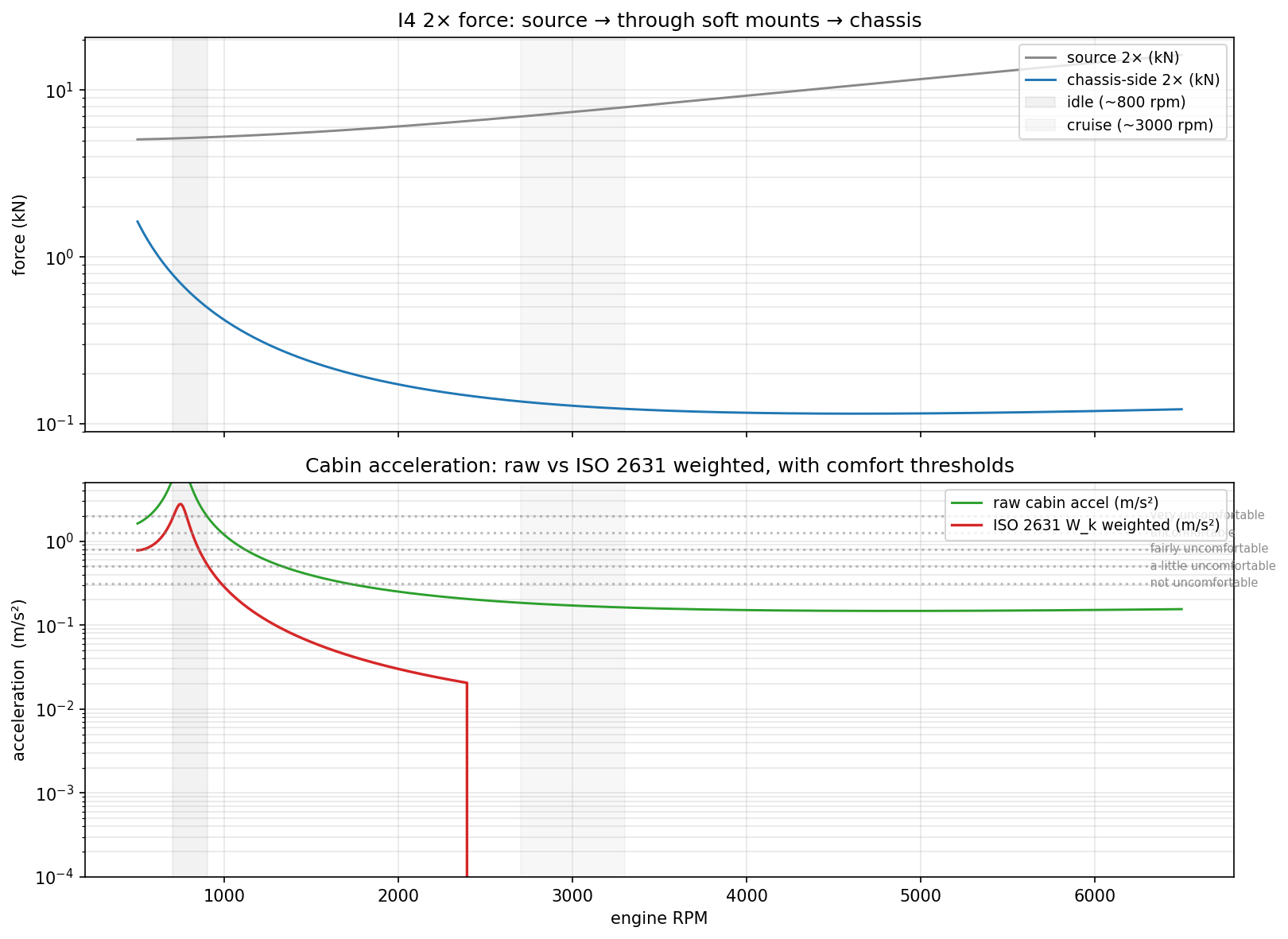
- The I4 (The Standard Workhorse)
The most common engine in the world, and the one we’ve analyzed the most in the e-book.
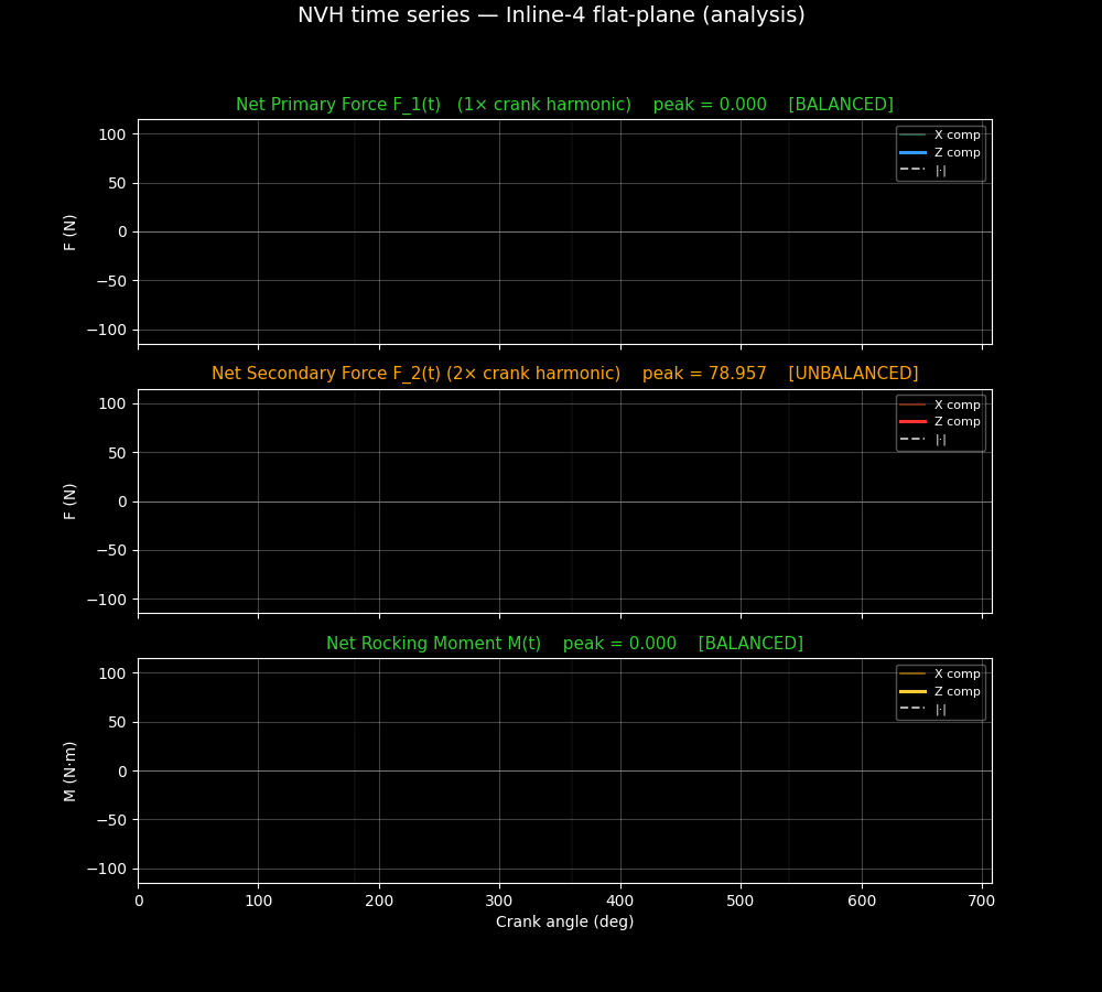
- The Math: Primary forces cancel, but Secondary forces reinforced. * The Issue: At $2\times$ engine speed, all four pistons are accelerating at the same time in a way that doesn’t cancel out. This creates a vertical “blur.”
- The Sound: Generally “generic.” In larger displacements (2.2L+), manufacturers add twin counter-rotating balance shafts (Lanchester balancers) to kill that $2\times$ buzz.
cd cadquery-blender-i4-analysis && make scene && make still FRAME=15
#scp jalcocert@192.168.1.2:/home/jalcocert/mbsd/z-cad-render/cadquery-blender-i4-analysis/render/i4_analysis_still_0015.png .
tmux new-session -d -s cad "make all" #if you will be leaving this for the night
scp jalcocert@192.168.1.2:/home/jalcocert/mbsd/z-cad-render/cadquery-blender-i4-analysis/render/i4_analysis.mp4 .

ffmpeg -stream_loop 14 -i i4_analysis.mp4 -c copy i4_analysis_output.mp4
Smoke-tested output:
|F_primary| peak = 0.0000 N |F_secondary| peak = 78.9568 N |M_rocking| peak = 0.0000 N·m 135 GIF frames (40 per subplot + 15 hold) → 800 KB GIF
Open render/i4_nvh_timeseries.gif and you should see: top panel stays flat at 0 (BALANCED, green), middle panel’s red Fz line draws four full sine cycles with peak ±79 N (UNBALANCED, orange), bottom panel stays flat at 0 (BALANCED, green).
That’s the I4 NVH story written in pure 2D, totally independent of the 3D Blender visualization — two independent checks of the same math.
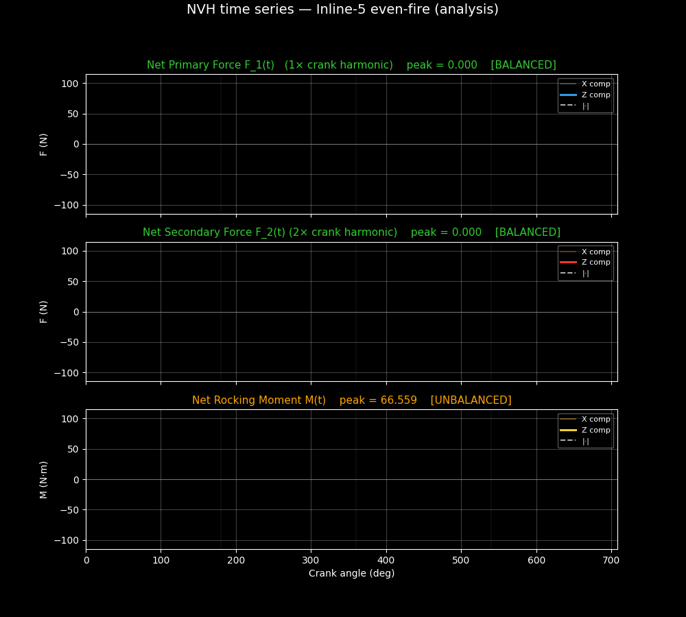
- The I5 (The Exotic Warble)
Famously used by Audi, Volvo, and early 5-cylinder VWs.
- The Math: With pins every 72°, the I5 is much better balanced than an I4. It has zero net primary and secondary force shake.
- The Issue: Like the I3, it has a Rocking Couple, but because the engine is longer and the pins are “spread out” around the circle, the rock is much smaller and “snakes” in a circular pattern rather than a simple vertical nod.
- The Sound: Iconic $144^\circ$ firing interval. It sounds like a “Baby V10” because the harmonics are similar.
cd cadquery-blender-i5-analysis && make scene && make still FRAME=15
#scp jalcocert@192.168.1.2:/home/jalcocert/mbsd/z-cad-render/cadquery-blender-i5-analysis/render/i5_analysis_still_0015.png .
tmux new-session -d -s cad "make all" #if you will be leaving this for the night
scp jalcocert@192.168.1.2:/home/jalcocert/mbsd/z-cad-render/cadquery-blender-i5-analysis/render/i5_analysis.mp4 .

ffmpeg -stream_loop 14 -i i5_analysis.mp4 -c copy i5_analysis_output.mp4
Build it with cd cadquery-blender-i5-analysis && make scene && make plot && make still FRAME=15.
The two-rocking-couple yellow arrows will show the mixed-frequency throbbing pattern (4 main 2× cycles modulated by a slower 1× envelope) — visually distinct from both the I4’s clean vertical pulsing and the V6-90’s similar-but-different rocking flavour.
Yes, those numbers are perfectly consistent with the unique physics of the Inline-5. You have mathematically captured exactly what gives the I5 its “exotic” reputation: it is an engine that is smooth in its hands (Force) but restless in its feet (Moment).
Here is why those specific results make sense for an I5 with $72^\circ$ crankpin spacing:
1. $|F_{primary}| = 0$ and $|F_{secondary}| = 0$
In an I4, the secondary forces ($2\times$) add up because the pistons move in pairs that reinforce each other. In an I5, the $72^\circ$ spacing is the “Magic Number.”
When you look at the force phasors for 5 cylinders spaced evenly around a circle:
- Primary: They form a perfect pentagon. The vector sum is zero.
- Secondary: The angles become $2 \times 72^\circ = 144^\circ$. If you plot 5 vectors at $144^\circ$ intervals, they also form a perfect (though “star-shaped”) pentagon. The sum remains zero.
This is why an I5 doesn’t have the vertical “buzz” of an I4. In terms of pure “shaking force,” an I5 is as balanced as an I6.
2. $|M_{rocking}| = 66.5595$ N·m
This is the “Price of Admission” for the I5. Even though the forces cancel, they act at different points along the crankshaft.
Unlike the I4 or I6, the I5 is axially asymmetric. Cylinder 1 (at the front) doesn’t have a “twin” at the back (Cylinder 5) doing the exact same thing at the exact same time.
- When Cylinder 1 pushes up, the other cylinders aren’t perfectly positioned to stop the engine from tilting.
- This creates a Primary Rocking Couple (the $66.5$ N·m you seeing).
- It also creates a Secondary Rocking Couple (though usually smaller), contributing to that complex, 3D “snaking” vibration.
Comparison of the “Analysis Mode” (I4 vs I5)
If you rendered these two side-by-side in your 3D Analysis Mode, the contrast would be a powerful educational tool:
| Feature | Inline-4 Analysis | Inline-5 Analysis |
|---|---|---|
| Primary Vector (Blue) | Zero (Static dot) | Zero (Static dot) |
| Secondary Vector (Red) | Strong Vertical Pulse | Zero (Static dot) |
| Rocking Arrows | Zero | Visible “See-Saw” motion |
| NVH Identity | The “Vertical Hopper” | The “End-to-End Rocker” |
The I5 “Warble”
The $66.5$ N·m peak explains why the I5 needs specific motor mount tuning. The engine isn’t trying to jump out of the car; it’s trying to twist.
This twisting, combined with the $144^\circ$ firing interval, is what creates the famous Audi/Volvo “warble”—the sound of the block physically reacting to those rocking moments.
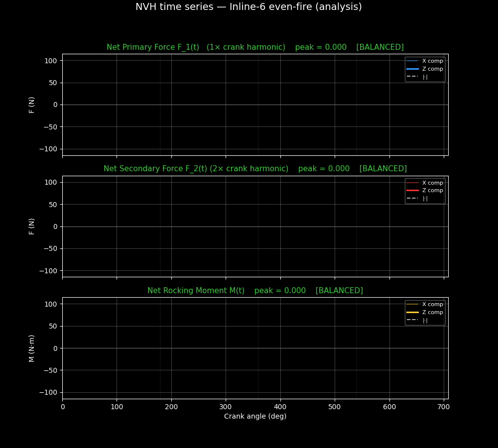
- The I6 (The Mechanical Holy Grail)
The Straight-6 is the “Gold Standard” of engine design.
- The Math: It is essentially two I3s mirrored. The rocking moment of the front 3 cylinders is perfectly cancelled by the rocking moment of the rear 3 cylinders.
- The Result: Zero Primary Force, Zero Primary Moment, Zero Secondary Force, Zero Secondary Moment.
- Why not use it always? It is very long. It is hard to fit transversely (front-wheel drive) and takes up massive space under the hood.
cd cadquery-blender-i6-analysis && make scene && make still FRAME=15
#scp jalcocert@192.168.1.2:/home/jalcocert/mbsd/z-cad-render/cadquery-blender-i6-analysis/render/i6_analysis_still_0015.png .
tmux new-session -d -s cad "make all" #if you will be leaving this for the night
scp jalcocert@192.168.1.2:/home/jalcocert/mbsd/z-cad-render/cadquery-blender-i6-analysis/render/i6_analysis.mp4 .

ffmpeg -stream_loop 14 -i i6_analysis.mp4 -c copy i6_analysis_output.mp4
Why the I6 wins the NVH war
In our Phasor Framework, the I6 is the only one where the vectors sum to zero for both the Force sum and the Moment sum across both 1× and 2× harmonics.
| Engine | Force Sum ($1\times$) | Moment Sum ($1\times$) | Force Sum ($2\times$) | Moment Sum ($2\times$) |
|---|---|---|---|---|
| I3 | 0 | ❌ | 0 | ❌ |
| I4 | 0 | 0 | ❌ | 0 |
| I5 | 0 | ❌ (small) | 0 | ❌ (small) |
| I6 | 0 | 0 | 0 | 0 |
Conclusions
This gave you some idea?
 Consulting Services
 DIY via ebooks
FAQ
When analyzing an Inline-4 (I4), the term “secondary momentum” (or more accurately, the secondary rocking couple/moment) is one of the most elegant parts of the math because, in a standard symmetrical I4, it is zero.
Here is why that $0.0000$ N·m result for the rocking moment makes perfect sense from a physics perspective, especially when contrasted against the secondary force.
- The Symmetry of the I4
In a standard I4, the crankpins are arranged at $[0^\circ, 180^\circ, 180^\circ, 0^\circ]$.
- Pistons 1 & 4 (the outside pair) move together.
- Pistons 2 & 3 (the inside pair) move together, exactly opposite to the outside pair.
Because the engine is perfectly symmetrical about its center point (between cylinders 2 and 3), the “leverage” from the front half is exactly cancelled by the “leverage” from the rear half.
- Force vs. Moment: The Crucial Distinction
It is a common point of confusion: How can there be a secondary force but no secondary moment?
- Secondary Force ($F_{secondary}$): All four pistons reach their maximum upward acceleration at the same time and their maximum downward acceleration at the same time (twice per revolution). Because they all push in the same direction, the forces add up. This creates the vertical “buzz.”
- Secondary Moment ($M_{secondary}$): To have a moment (a rocking couple), the forces on one side of the engine center would have to be different from the other. Since Cylinder 1 is identical to Cylinder 4, and Cylinder 2 is identical to Cylinder 3, there is no “see-saw” effect. The net tendency to tilt end-to-end is zero.
- Comparison Table: I3 vs. I4 vs. I6
| Engine | Secondary Force ($F$) | Secondary Moment ($M$) | Visual Behavior |
|---|---|---|---|
| I3 | Balanced (0) | Unbalanced | The engine “nods” end-to-end. |
| I4 | Unbalanced | Balanced (0) | The engine “hops” vertically. |
| I6 | Balanced (0) | Balanced (0) | Perfectly still. |
- When does the I4 have a Secondary Moment?
In the real world, an I4 only develops a secondary rocking moment if you break the symmetry.
This happens in:
- Asymmetric Firing/Crank Geometry: Rare in production cars, but used in some racing applications.
- Manufacturing Tolerances: If piston 1 is significantly heavier than piston 4, a small residual moment appears (this is why high-end “blueprinted” engines feel smoother).
- V-Engines: A V8 Flat-Plane (which is two I4s) can actually have secondary moments if the bank angle or the axial offset of the cylinders isn’t perfectly managed.
Summary for your “X-Ray” Mode
In your 135-frame GIF for the I4:
- Force Plot: You will see a strong, high-frequency Red vector (Secondary Force) oscillating vertically.
- Moment Plot: You will see a flat line at zero.